|
Table: Structure, function and applications of various systems for decentralized solid retention [Somme2009] (Continued) |
Construction |
Operating Principle |
Field of Application |
|
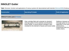
INNOLET-Gutter grate [FI-Sieke] |
|
(Image: Decentralized solids retention) |
Filter cartridge filled with substrate for standard drainage gutters for fine particles and dissolved heavy metals. A coarse particle cartridge is also included for the retention of leaves and coarse … |
|
|
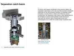
(Image: Separation catch basin) Of all the catch basins introduced in the previous tables, the separation catch basin is the only one that has been developed especially for the decentralised retention of settleable solids. Therefore, it is described in detail in the following section.
Furthermore, the separation catch basin is also appropriate for the limitation of severe water pollution levels because it interrupts the relevant input of particulate … |
|
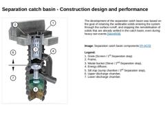
(Image: Separation catch basin components) The development of the separation catch basin was based on the goal of retaining the settleable solids entering the system through the surface runoff, and stopping the remobilisation of solids that are already settled in the catch basin, even during heavy rain events [SteinR08]. Image: Separation catch basin components [FI-ACO] Legend:
1. Grate (Screen / 1st Separation step)
2. Frame,
3. Waste bucket (Sieve / … |
|
(Video: Video:Operating principle of the separation catch basin) |
|
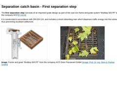
The first separation step iconsists of an improved grate design as part of the cast iron frame and grate system “Multitop 500 PF” by the company ACO [FI-ACO]. It is constructed in accordance with DIN EN 124, and includes a shock absorbing riser which disperses traffic energy into the subsoil thus preventing localised settlement. (Image: Separation catch basin - frame and grate) (Image: Catch basin grate) : Frame and grate “Multitop 500 PF” from … |
|
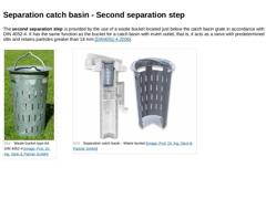
The second separation step is provided by the use of a waste bucket located just below the catch basin grate in accordance with DIN 4052-4. It has the same function as the bucket for a catch basin with invert outlet, that is, it acts as a sieve with predetermined slits and retains particles greater than 16 mm [DIN4052-4:2006]. (Image: Waste bucket type A4 DIN 4052-4) (Image: Separation catch basin - waste bucket) |
|
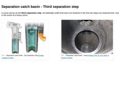
A sump serves as the third separation step. All settleable solids that were not retained in the first two steps are retained here, even in the event of a heavy storm. (Image: Separation catch basin - 3rd separation step) (Image: Separation catch basin - sump) |
|
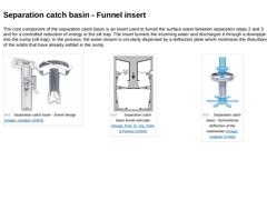
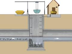
The core component of the separation catch basin is an insert used to funnel the surface water between separation steps 2 and 3 and for a controlled reduction of energy in the silt trap. The insert funnels the incoming water and discharges it through a downpipe into the sump (silt trap). In the process, the water stream is circularly dispersed by a deflection plate which minimises the disturbance of the solids that have already settled in the sump. |
|
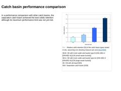
In a performance comparison with other catch basins, the separation catch basin achieved the best solids retention although its maximum performance limit was not yet met. (Image: Relative solid retention [%] of the catch basin types tested in-situ, assuming one cleaning measure per year) |
|
This module deals with the topics of semi-centralized and decentralized sedimentation of solids. One focus is on decentralized sedimentation using road catch basins. The different designs and modes of operation of these structures are explained and their performance is demonstrated. After completing this module, you will have knowledge regarding: - constructive measures to prevent sedimentation;
- procedural principles of these constructive measures.
|
|
Pressure lines, that is “lines for the transport of sewage under pressure” are cleaned using methods. |
|
Physical methods aim at an increase of the sewage flow velocity for cleaning purposes by the addition of pressurised air. Flushing is performed two to four times a day, or more often if required, by blowing air into the pressure pipe system. Thus, the flow cross section in the pressure pipelines is decreased. Due to the increased sewage velocity, deposits are stirred up and transported further downstream. |
|
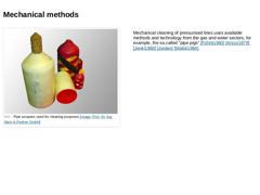
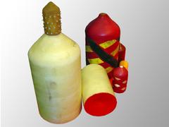
(Image: Pipe scrapers used for cleaning purposes) Mechanical cleaning of pressurised lines uses available methods and technology from the gas and water sectors, for example, the so.called "pipe pigs" [Führb1980] [Arsco1979] [Jenki1968] [Jordan] [Walsk1984]. |
|
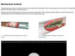
The pipe pig closes the cross section of the line and is either forced through the line to be cleaned by the sewer flow, or through the addition of pressure (water or pressurised air). Inserting and removing the pipe pig is performed using locks (pig traps). This procedure requires fittings, such as ball valves and isolating valves that can entirely open and close the cross section of the pipe. (Image: Operational principle of a pipe pig) |
|
According to DIN EN 752, an inverted siphon is a section of a depressed sewer or gravity sewer, which operates under pressure as it is installed lower than the upstream, and the downstream sections of the pipe. It is a system used to pass under obstacles such as streams or structures [EN752:2008]. When inverted siphons discharge wastewater and/or stormwater, they usually cannot be operated entirely free of agglomerations and deposits [Loren2003]. The … |
|
The following methods are used to remove or to avoid the formation of these deposits: -
High pressure cleaning with ejector nozzles
-
Scraper methods
Furthermore, there is the possibility to influence the flow velocity by constructive measures, such as: -
Flushing pump systems, and
-
Air-cushion inverted siphons.
|
|
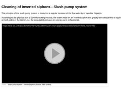
The principle of the slush pump system is based on a regular increase of the flow velocity to mobilise deposits. According to the physical law of communicating vessels, the water head for an inverted siphon in a gravity line without flow is equal on both sides of the siphon, i.e. the associated pressure or energy curve is horizontal. (Video: Slush pump system - Inverted siphon) |
|
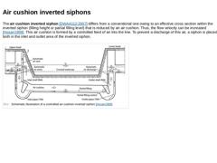
The air cushion inverted siphon [DWAA112:2007] differs from a conventional one owing to an effective cross section within the inverted siphon (filling height or partial filling level) that is reduced by an air cushion. Thus, the flow velocity can be increased [Hosan1998]. This air cushion is formed by a controlled feed of air into the line. To prevent a discharge of this air, a siphon is placed both in the inlet and outlet area of the inverted siphon. |

|
Currently, high pressure cleaning is the most commonly used method to clean sewers. According to a survey by Stein in 2000, the use of high pressure cleaning in North Rhine-Westfalia (NRW), Germany, amounted to more than 95% of overall cleaning measures [SteinD00a]. Throughout Germany, this method was used in about 90% of all cases [Geib2002]. Hence the use of other cleaning methods in Germany is not more than 10%.
|
|
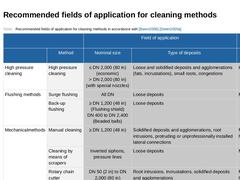
(Table: Recommended fields of application for cleaning methods in accordance with [Baren2006][Dettm2005a]) |
|
Special conditions apply to the cleaning of pressure pipes. This module is therefore explicitly dedicated to the procedures and methods used for cleaning this type of pipe. After completing this module, you will have knowledge of: - procedures for cleaning pressure pipelines and
- procedural principles.
|
|
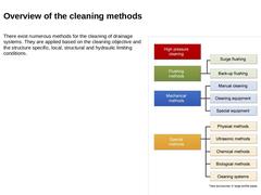
There exist numerous methods for the cleaning of drainage systems. They are applied based on the cleaning objective and the structure specific, local, structural and hydraulic limiting conditions.
(Image: Overview of the drain and sewer cleaning methods as per [Führb1980]) |
|
Selection of cleaning measures must be in accordance with [DIN EN 14654-1] and should also take into account the technical feasibility and economic viability, along with the following boundary conditions: - Type, quantity and composition of the deposits and obstacles
- Access to the location to be cleaned
- Road type and traffic situation
- Depth of cover
- Cross section and dimensions
- Change of cross section or displacement
- Material
- Structural condition
- Volumetric …
|
|
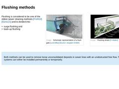
Flushing is considered to be one of the oldest sewer cleaning methods [Frühl10] [Gürsc21] and is divided into: -
surge flushing and
-
back-up flushing
(Image: Schematic representation of a flush gate) Both methods can be used to remove loose unconsolidated deposits in sewer lines with an unobstructed free flow. The flushing systems can either be installed permanently or temporarily. |
|
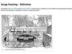
According to [EN752:2008] and [DIN EN 14654-1] surge flushing is defined as “the creation of a temporarily increased discharge to remove any obstacles or deposits in drains or sewers channels.”
(Image: Tiber Creek Sewer Flush Gates) |