|
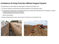
The specifications for trench depths and slope angles of unlined trenches apply only if: |
|
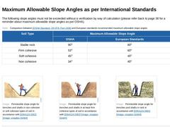
The following slope angles must not be exceeded without a verification by way of calculation (please refer back to page 38 for a reminder about maximum allowable slope angles as per OSHA). (Table: Maximum allowable slope angle comparison) (Image: Permissible slope angle for trenches and shafts in non-cohesive or soft cohesive types of soil in accordance with [DIN4124c]) (Image: Permissible slope angle for trenches and shafts in at least firm cohesive … |
|
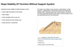
Imperative to the stability of artificial slopes are the: -
slope angle (inclination of the slope),
-
slope height,
-
shear strength of the in situ soil,
-
forces acting from the outside, and
-
water pressure, in particular.
If a slope is not stable, it may result in a slope failure. In that process, a sliding body is formed that moves down along the sliding surface. Warning signs that a slope failure is imminent are increasing deformations of the slope. … |
|
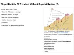
A slope failure occurs when: -
the angle of the slope is too large;
-
the slope height is too large;
-
low shear strength of the soil;
-
loading above the slope;
-
vibrations;
-
changes to the groundwater conditions.
(Image: Moments with an impact onto a slope calculation according to the slice method) |
|
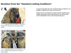
(Image: Unshored trench with a depth of > 1.25 m/4 ft = Danger to life!) (Image: Only partly shored trench with a depth of > 1.25 m/4 ft = Danger to life!) In cases of deviation from the “standard limiting conditions”, the stability of sloped trench walls is to be proven. Slopes have to be checked at regular intervals regarding their stability (particularly after longer periods of non activity, after severe precipitation events, and during thawing … |
|
|
|
The selection of an appropriate trench support system is subject to local limiting conditions (as e.g. the type of soil, the groundwater level, the dimensions of the trench, the number of services and lateral connections, the condition of adjacent areas or the expected loads imposed onto the soil due to construction equipment etc.). Thus, at least the following data have to be known for the selection, and potential dimensioning, of the trench support … |
|
It is important to note that the type of trench support system is taken into account during the structural calculation of the pipe, and must never be changed without the approval of the structural engineer. |
|
The most common types of trench support systems include: -
Horizontal timber shoring
-
Vertical trench shoring using timber or steel sheets (“Tight sheeting” means a continuous row of wood or steel sheets in close contact to provide a tight wall, but is not driven as with sheet piling)
-
Vertical trench shoring using sheet piles ( “Sheet piling” means a continuous row of steel piles driven in close contact to provide a tight wall to resist lateral pressure …
|
|
Horizontal timber shoring is used in groundwater-free subsoil for trench depths of 10 ft to 16 ft (3 m to 5 m). The trench faces, in line with the excavation process, are gradually lined from the top down with closely spaced horizontal timber shoring, sheet piles or similar, which are normally secured using vertical wale timbers and supported by braces. (Image: Standard horizontal shoring (fixing material is not illustrated here) in accordance with [… |
|
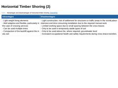
(Table: Advantages and disadvantages of horizontal timber shoring) |
|
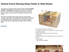
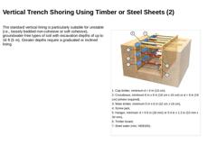
The process of vertical trench shoring involves installing timber shoring or sheet piles gradually in line with the excavation process. In the case of soft, cohesive types of soil, they are driven at least 1 ft (0.3 m) into the subsoil at the base of the trench. The earth- and traffic loads acting upon the vertical timber shoring or sheet piles are transferred to horizontal wale timbers or steel girders that are installed in line with the excavation … |
|
The standard vertical lining is particularly suitable for unstable (i.e., loosely bedded non-cohesive or soft cohesive), groundwater-free types of soil with excavation depths of up to 16 ft (5 m). Greater depths require a graduated or inclined lining. (Image: Vertical trench shoring using timber shoring in accordance with [DIN4124:2002]) |
|
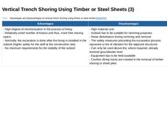
(Table: Advantages and disadvantages of vertical trench shoring using timber or steel sheets) |
|
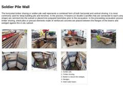
The horizontal timber shoring or soldier pile wall represents a combined form of both horizontal and vertical shoring. It is most commonly used for deep building pits and trenches. In the process, H-beams (or double U-profiles that are connected to each using straps) are rammed into the subsoil or placed into prepared boreholes prior to the excavation. In the proceeding excavation process, timber shoring, sheet piles or precast elements made of reinforced … |
|
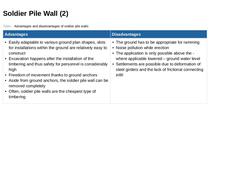
(Table: Advantages and disadvantages of soldier pile walls) |
|
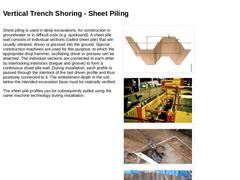
Sheet piling is used in deep excavations, for construction in groundwater or in difficult soils (e.g. quicksand). A sheet pile wall consists of individual sections (called sheet pile) that are usually vibrated, driven or pressed into the ground. Special construction machines are used for this purpose, to which the appropriate drop hammer, oscillating driver or presses can be attached. The individual sections are connected to each other by interlocking … |
|
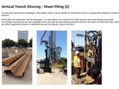
To make the interlock area watertight, either plastic seals must be inserted or the interlock area is subsequently welded or sealed by injection. Sheet piles are among the "soft shoring types", i.e. they deform as a result of the earth pressure generated during excavation. Accordingly, bracing must be done gradually and in line with the proceeding excavation process by means of horizontal waler which are either supported by struts or rearwards secured … |
|
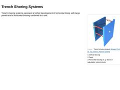
(Image: Trench shoring system) Trench shoring systems represent a further development of horizontal lining, with large panels and a horizontal bracing combined to a unit. |
|
|
|
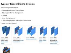
Trench shoring systems include: -
Centre-supported trench shoring system
-
Edge-supported trench shoring system
-
Drag box
-
Linear Shoring Systems
-
Linear Shoring Systems - with Boogie Car/roller frame
-
Sheet Pile Frame Systems
(Image: Centre-supported trench shoring system) (Image: Edge-supported trench shoring systems) (Image: Dragboxes) (Image: Linear shoring systems) (Image: Linear shoring systems with Boogie Car/roller frame) (Image: Sheet Pile Frame … |
|
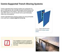
Centre-supported trench shoring systems are composed of a pair of metal panels with centrally arranged vertical braces that are supported by cross braces. They have to be connected to each other when in use and should not be used individually under any circumstances. Centre-supported trench shoring systems are only permissible to be used up to a trench depth of 13 ft (4 m). (Image: Centre-supported trench shoring system) |
|
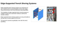
Edge-supported trench shoring systems are composed of a pair of panels which are joined together at the outer edges using vertical braces and cross braces(normally adjustable). The installation of edge-supported trench shoring systems is suitable for both the cut and lower method as well as the insertion method. Edge-supported trench shoring systems are only permissible to be used up to a trench depth of 20 ft (6 m). The removal is carried out gradually … |
|
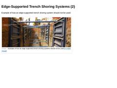
Example of how an edge-supported trench shoring system should not be used: (Image: Example of how an edge-supported trench shoring systems should not be used) |
|
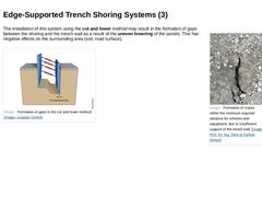
(Image: Formation of cracks within the minimum required distance for vehicles and equipment, due to insufficient support of the trench wall) The installation of this system using the cut and lower method may result in the formation of gaps between the shoring and the trench wall as a result of the uneven lowering of the panels. This has negative effects on the surrounding area (soil, road surface). (Image: Formation of gaps in the cut and lower method) |