|

|
|
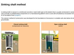
A sinking shaft or caisson is a reinforced concrete or steel shaft open at the bottom that is usually constructed in sections of in-cast concrete or prefabricated components on a manufacturing platform and is sunk with simultaneous excavation of the core to its foundation level [Linge97]. The caisson method of construction was developed for the foundations of structures in unstable soils also below the level of the groundwater. |
|
Closed sinking shaft |
|
|
|
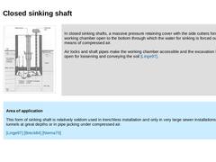
(Image: Closed sinking shaft during building the 26 m deep starting shaft (dimensions 7.5 m x 14 m) for the utility tunnel "Energieversorgungstunnel Kieler Förde" (Bild 9.2.1.3.1) (Bild 9.2.1.3.1) (Bild 2.2.4) [Holzm93b]) |
In closed sinking shafts, a massive pressure retaining cover with the side cutters forms a working chamber open to the bottom through which the water for sinking is forced out by means of compressed air. Air locks and shaft pipes … |
|
|
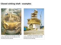
(Image: Creating the exit openings in a closed sinking shaft using in cast concrete [Biele79b] - Recesses of the exit opening) (Image: Creating the exit openings in a closed sinking shaft using in cast concrete [Biele79b] - Bricking up the exit opening) |
|
|
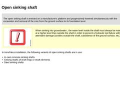
The open sinking shaft is erected on a manufacturer's platform and progressively lowered simultaneously with the excavation and removal of the core from the ground surface to its foundation level. | | | (Image: Attention!)
When sinking into groundwater , the water level inside the shaft must always be maintained at a higher level than outside the shaft in order to prevent a hydraulic soil failure with its attendant damage (cavities outside the shaft, … |
|
|
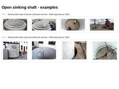
(Table: Sinking shaft made of precast reinforced concrete - Shaft rings) (Table: Sinking shaft made of precast reinforced concrete - Shaft rings) |
|
|
Shaft sinking
|
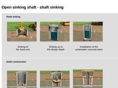
(Image: Construction phases of the trenchless installation of sewers on the model of microtunnelling - Phase 1 (Sinking of the shaft): Sinking of the base unit of the shaft) |
|
Sinking of
the base unit |
|
|
(Image: Construction phases of the trenchless installation of sewers on the model of microtunnelling - Phase 1 (Sinking of the shaft): Sinking up to the design depth) |
|
Sinking up to
the design depth |
|
|
(Image: Construction phases of … |
|
|
|
|
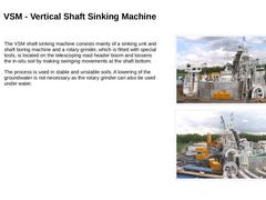
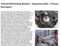
The VSM shaft sinking machine consists mainly of a sinking unit and shaft boring machine and a rotary grinder, which is fitted with special tools, is located on the telescoping road header boom and loosens the in-situ soil by making swinging movements at the shaft bottom. The process is used in stable and unstable soils. A lowering of the groundwater is not necessary as the rotary grinder can also be used under water. |
|
(Image: VSM shaft sinking … |
|
|
|
The shaft boring machine is lowered into the launch shaft structure and attached firmly to the shaft with its three machine arms. A rotating cutting drum equipped with chisel tools is attached to a telescopic boom. This roadheader excavates and breaks the soil at the base of the shaft. The roadheader is telescopic, and can swivel up and down or rotate. Hence, the entire cross-section of the shaft plus an overcut can be excavated gradually. The excavated … |
|
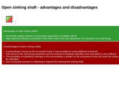
| (Image: Pros and cons) | | Advantages of open sinking shafts: - Technically simple method of construction especially in unstable subsoil
- High economic efficiency (reduction of the fixed costs of the site equipment, the utilization as a final lining)
| | Disadvantages of open sinking shafts: - In groundwater, drying out the excavation base is only possible by using additional measures
- The control of the soil during excavation and the removal of obstacles (boulders …
|
|
|
|

|
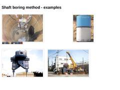
The shaft boring methods belong to the large diameter boring methods in shallow and deep boring or drilling technology in which the construction of the shaft takes place from the surface without the use of personnel in the base [Arnol93]. |
|
|
|
(Image: Attention!)
With this method, the disadvantages of pressing sinking are mostly eliminated and also difficult geological subsoil conditions can be overcome and the sinking can be rationalized and mostly … |
|
|
(Image: CCB method: shaft boring method with reinforced concrete upper shaft rings for use in soil [FI-KCMM] - Inserting the core boring crown with torsion resisting connected reinforced concrete shaft rings in the rotary table) (Image: CCB method: shaft boring method with reinforced concrete upper shaft rings for use in soil [FI-KCMM] - Reinforced concrete shaft ring with removable steel upper shaft ring placed on top) (Image: MS-HBM-CR method (… |

|
|
|
|
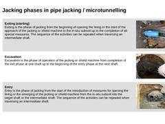
(Image: View into the starting pit - Positioning of the pipe jacking machine in the entry opening)
Exiting (starting)
Exiting is the phase of jacking from the beginning of opening the lining or the start of the approach of the jacking or shield machine to the in-situ subsoil up to the completion of all special measures. The sequence of the activities can be repeated when traversing an intermediate shaft. |
|
(Image: Wear when using a shield machine … |
|
|
|
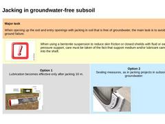
Major task When opening up the exit and entry openings with jacking in soil that is free of groundwater, the main task is to avoid ground failure. |
|
(Image: Attention!)
When using a bentonite suspension to reduce skin friction or closed shields with fluid or earth pressure support, care must be taken of the fact that support medium and/or lubricant cannot run into the shaft. |
|
Option 1
Lubrication becomes effective only after jacking 10 m. (Image: T.… |
|

|
(Table: Creation of the exit and entry openings with reference to the type of lining [FI-Steina]) |
|
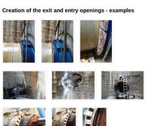
(Image: Exit opening with dopple elastomer ring seal and recoil brake) (Image: Exit opening with dopple elastomer ring seal and recoil brake) (Image: Exit opening with dopple elastomer ring seal and recoil brake - Detail) (Image: Entry opening in a target pit of spray concrete without groundwater - Opening has a limited reinforcement ratio) (Image: Entry opening in a target pit of spray concrete without groundwater - Breakthrough of the tunneling … |
|
|
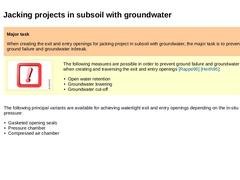
Major task When creating the exit and entry openings for jacking project in subsoil with groundwater, the major task is to prevent ground failure and groundwater inbreak. |
|
(Image: Attention!) |
The following measures are possible in order to prevent ground failure and groundwater inflows when creating and traversing the exit and entry openings [Rappe96] [Herth95]: -
Open water retention
-
Groundwater lowering
-
Groundwater cut-off
|
|
The following principal … |
|
|
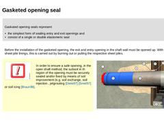
Gaskated opening seals represent -
the simplest form of sealing entry and exit openings and
-
consist of a single or double elastomeric seal
|
Before the installation of the gasketed opening, the exit and entry opening in the shaft wall must be opened up. With steel sheet pile linings, this is carried out by burning out or pulling the respective sheet piles. |
|
(Image: Attention!)
In order to ensure a safe opening, in the open shaft method, the subsoil … |
|
|
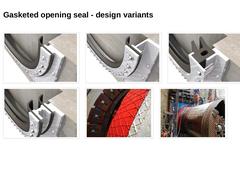
(Image: Elastomeric seal ring for gasketed openings for sealing exit- and entry openings - Single seal (fixed with loose flange)) (Image: Elastomeric seal ring for gasketed openings for sealing exit- and entry openings - Single seal) (Image: Elastomeric seal ring for gasketed openings for sealing exit- and entry openings - Double seal) (Image: Elastomeric seal ring for gasketed openings for sealing exit- and entry openings - Double single seal) (Image: … |
|
|
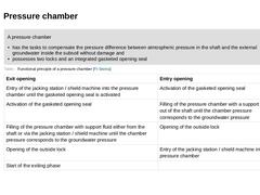
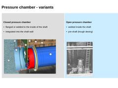
A pressure chamber - has the tasks to compensate the pressure difference between atmospheric pressure in the shaft and the external groundwater inside the subsoil without damage and
- possesses two locks and an integrated gasketed opening seal
| | (Table: Functional principle of a pressure chamber [FI-Steina]) |
|
|
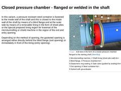
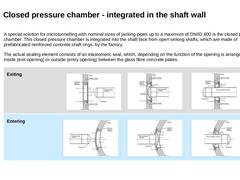
In this variant, a pressure resistant steel container is fastened to the inside wall of the shaft and this is closed to the inside wall of the shaft by means of a blind flange and at the outer side by means of a removable lining in the form of sheet piles or the special prepared lining region for traversal of the microtunnelling or shield machine in the region of the exit and entry opening. Depending on the method of opening, the gasketed opening … |
|
Closed pressure chamber (Image: Exit lock in the form of a closed pressure chamber flanged to the starting shaft [Stein05a]) |
Open pressure chamber
(Image: Open pressure chamber welded to the inside of the shaft) |
|
|
|
A special solution for microtunnelling with nominal sizes of jacking pipes up to a maximum of DN/ID 800 is the closed pressure chamber. This closed pressure chamber is integrated into the shaft face from open sinking shafts, which are made of prefabricated reinforced concrete shaft rings, by the factory. The actual sealing element consists of an elastomeric seal, which, depending on the function of the opening is arranged either inside (exit opening) … |
|
