|

| (Image: Pros and cons) | General information - Applicable for long sections depending on the local situation
- It is possible to apply lining pipes made of HD-PE, PP as well as PVC
- No pipe joints (generally welded)
- Lining pipe can be controlled and examined before installation, e.g. with regard to its water tightness
- Lining pipes made of HD-PE, PP or PVC, respectively are highly resistant to mechanical and chemical attacks
- It is possible to rehabilitate …
|
|
|
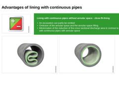
| (Image: Pros and cons) | Lining with continuous pipes without annular space - close-fit-lining - An excavation can partly be omitted
- Omission of the annular space and the annular space filling
- Minimization of the reduction of the cross sectional discharge area in contrast to lining with continuous pipes with annular space
| | (Image: Deformation process – lining pipe pre-deformed) | (Image: Deformation process - liner redeformed) |
|
|
|
| (Image: Pros and cons) | General information - In the non-accessible nominal size area, the complex recreation of the laterals is needed, generally applying the open cut method
- Reduction of the cross sectional discharge area of the sewer to be rehabilitated
- In the case of strong water infiltration, the damage areas have to be pre-sealed
- In general, the sewer to be rehabilitated including its laterals have to be taken out of operation for the time of …
|
|
|
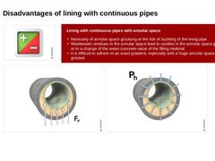
| (Image: Pros and cons) | Lining with continuous pipes with annular space - Necessity of annular space groutung at the risk of buckling of the lining pipe
- Wastewater residues in the annular space lead to cavities in the annular space grouting or to a change of the water-concrete-value of the filling material
- It is difficult to adhere to an exact gradient, especially with a huge annular space to be grouted
| | (Image: Buoyancy force Fv with reference to [… |
|
|
|
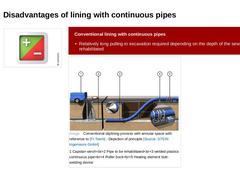
| (Image: Pros and cons) | Conventional lining with continuous pipes - Relatively long pulling-in excavation required depending on the depth of the sewer to be rehabilitated
| | (Image: Conventional sliplining process with annular space with reference to [FI-Teerb] - Depiction of principle [Image: S&P GmbH]) |
|

|
|
|
This module deals with the basic principles of lining with continuous pipes processes as well as their terminological definitions, limiting conditions and areas of application. |

|
Today, supply and discharge lines are still predominantly installed by using the open-cut method: a trench is dug, the lines are installed. Under the protection of an embankment or sheeting and the trench is filled afterwards. In the face of the numerous disadvantages as well as the citizens' growing environmental consciousness in the future it is urgently necessary to take trenchless technology into account much stronger than until today as an alternative … |
|
|
(Image: Starting and target shafts) |
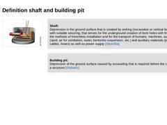
Shaft:
Depression in the ground surface that is created by sinking (excavation or vertical boring), with suitable securing, that serves for the underground creation of bore holes with the aid of the methods of trenchless installation and for the transport of humans, machines, substances (spoil, air for ventilation, water, bentonite suspension, etc.) and auxiliary materials (pipes, cables, hoses) as well as power … |
|
|
|
(Image: Starting and target shafts) |
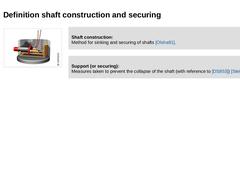
Shaft construction:
Method for sinking and securing of shafts [Olsha91]. |
|
|
|
Support (or securing):
Measures taken to prevent the collapse of the shaft (with reference to [DS853]) [Stein05a]. |
|
|
In trenchless installation, it is differentiated between: -
Starting shaft
-
Target shaft
-
Intermediate shaft
(Image: Construction phases of the trenchless installation of sewers on the model of microtunnelling - Phase 2 (Jacking)) |
|
|
(Image: Starting and target shafts) |
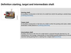
Starting shaft:
An auxiliary construction in the form of a shaft from which the jacking is started (based on [DS853]) [Stein05a]. |
Target shaft:
An auxiliary construction in the form of a shaft in which the jacking ends (also called destination shaft) (based on [DS853]) [Stein05a]. |
Intermediate shaft:
Auxiliary structure in the form of a shaft which is passed through planned (e.g. for maintenance, tool change, … |
|
|
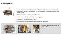
(Image: Starting and target shafts) For instance, in microtunnelling and pipe jacking, the following occurs at the starting shaft: -
Installation of the (main) jacking station and the abutment for introducing the jacking forces into the subsoil
-
Positioning the microtunnelling or shield machine
-
Installation of the fixed portions of the measuring system
-
Installation of the individual jacking pipes
-
Discharging the spoil excavated at the working face …
|
|
|
(Image: Starting and target shafts) |
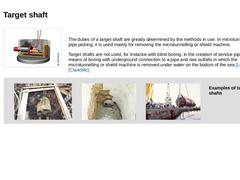
The duties of a target shaft are greatly determined by the methods in use. In microtunnelling and pipe jacking, it is used mainly for removing the microtunnelling or shield machine. Target shafts are not used, for instance with blind boring, in the creation of service pipes by means of boring with underground connection to a pipe and sea outfalls in which the microtunnelling or shield machine is removed under … |
|
|
|
(Image: Starting and target shafts) |
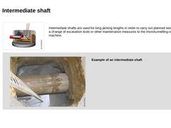
Intermediate shafts are used for long jacking lengths in order to carry out planned works such as a change of excavation tools or other maintenance measures to the microtunnelling or shield machine. |
|
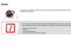
(Image: View into an intermediate shaft)
Example of an intermediate shaft |
|

|
|
|
| (Image: Planning) In trenchless installation, shafts are the only structures that must be installed in the open-cut method of construction. | | (Image: Attention!) | In the interest of minimising the environmental disturbance as well as the construction costs associated with this, great importance is attached to the following planning aspects: - Selection of the location
- Quantity
- Form and dimensions
- Shaft construction method and support.
|
|
|
|
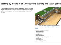
(Image: Attention!) In the lay out of the line the concerns of the jacking method to be applied must be taken into consideration: (Image: Utilisation of a shaft for several jackings [Stein05a]) The locality and the number of shafts are greatly influenced by the lay out of the planned line to be jacked. |
|
If starting and target shafts cannot be installed into the line axis directly, it is possible to create underground starting and target galleries, which are served from an access shaft sidewise of the line. (Image: Jacking with the aid of underground start and target galleries with reference to [Ito98] [Image: S&P GmbH]) |
|
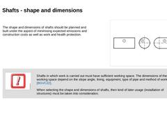
The shape and dimensions of shafts should be planned and built under the aspect of minimising expected emissions and construction costs as well as work and health protection. |
(Image: Cross sectional shapes of starting and target shafts) |
|
(Image: Attention!)
Shafts in which work is carried out must have sufficient working space. The dimensions of the working space depend on the slope angle, lining, equipment, type of pipe and method of working [… |
|
|
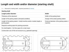
(Table: Dimensions of starting shafts - important parameters [FI-Steina]) | | (Image: Starting shaft dimensions for jacking pipes of 2.43 m lenght for rectangular shape of shaft and sheet pile wall lining for pre-defined microtunnelling or shield machine and jacking station [FI-Toyot])
| (Image: Starting shaft dimensions for jacking pipes of 2.43 m lenght for rectangular shape of shaft with semi-circular rounded faces and lining of liner plates for pre-… |
|
|
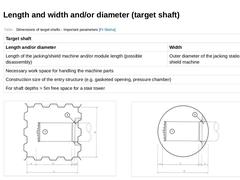
(Table: Dimensions of target shafts - important parameters [FI-Steina]) | | (Image: Target shaft dimensions for square shape of shaft and sheet pile wall lining for pre-defined microtunnelling or shield machine and jacking station [FI-Toyot])
| (Image: Target shaft dimensions for circular shape of shaft and lining with liner plates for pre-defined microtunnelling or shield machine and jacking station [FI-Toyot])
|
|
|
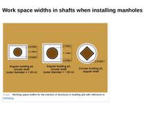
(Image: Working space widths for the erection of structures in building pits with reference to [TBG93a]) |
|
|
(Image: Attention!)
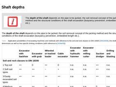
The depth of the shaft depends on the pipe to be jacked, the soil removal concept of the jacking method and the structural conditions of the shaft excavation (buoyancy prevention, embedded length etc.). |
|
The depth of the shaft depends on the pipe to be jacked, the soil removal concept of the jacking method and the structural conditions of the shaft excavation (buoyancy prevention, embedded length etc.). |
|
(Table: Application possibilities … |
|
|
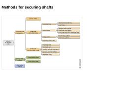
(Image: Methods for securing shafts [Stein05a]) |
