|

| (Image: Microtunnelling with hydraulic spoil removal in single phase jacking)
|
|
|
|
(Image: Examples of cross sectional shapes of starting shafts in microtunnelling [FI-Herreb] - Circular (open sinking shaft), jacking cylinder arranged parallel to the jacking pipe/to the microtunnelling machine)
|
|
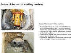
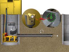
(Image: Entry of the microtunnelling machine into the target shaft)
|
|
Duties of the microtunnelling machine: - To create the necessary cavity so that the following pipe string can be pressed in with a minimum degree of soil deformation and …
|
|
|
|
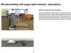
(Image: Technical components for microtunnelling with auger spoil removal in single phase jacking)
|
|
(Image: Equipment, possible arrangement of the components on the construction site and space requirement (approximately L × W = 22.0 × 4.0 m) in microtunnelling with auger spoil removal - top view (on the model of the jacking of pipes DN/ID 600, pipe length 2.0 m))
|
|
Method of operation and sequence Microtunnelling with auger spoil removal is characterized … |
|
|
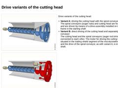
| (Image: Microtunnelling with auger spoil removal in single phase jacking - Variant: driving the cutting head with the spiral conveyor) | Drive variants of the cutting head: - Variant A: driving the cutting head with the spiral conveyor
The spiral conveyors (auger rods) and cutting head are fixed together and are driven by means of a drive assembly installed on the jacking frame in the starting shaft - Variant B: direct driving of the cutting head and separately …
|
|
|
|
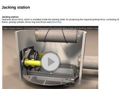
Jacking station:
Hydraulic thrust drive, which is installed inside the starting shaft, for producing the required jacking force, consisting of jacking frame, jacking cylinder, thrust ring and thrust wall (not found). (Video: Operating mode of a jacking station)
|
|

|
|
Area of application of microtunnelling methods with auger spoil removal: - nominal pipe size range of DN/ID 250 to DN/ID 1000 and jacking distances of up 150 m
- straight borings, usually loose soil of the soil classes L (stone classes up to S2) according to DIN 18319, in groundwater up to 6 m with additional equipment
- recommended area of application for a controlled mechanical support of the working face ≤ DN/ID 800
- the minimum depth of cover should …
|
|
|
|
(Image: Microtunnelling with hydraulic spoil removal in single phase jacking)
|
|
(Image: Basic equipment, possible arrangement components on the construction site and space requirements (ca. L × B = 35 × 4 m) for microtunnelling with hydraulic spoil removal - plan view (on the model of the jacking of pipes DN/ID 600, pipe length 2.0 m))
|
|
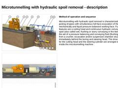
Method of operation and sequence Microtunnelling with hydraulic spoil removal is characterized by the jacking … |
|

|
(Video: Integrated high-pressure flushing system in the crusher space of the AVN microtunnelling machine) |
|
|
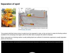
(Image: Separation of the spoil by a separation plant (compact plant MAB 300 with a solids capacity of 75 t/h) [FI-Schau]) (Image: Fluid circulation of microtunnelling by means of hydraulic spoil removal)
The pumped solid-fluid mixture (slurry) usually has to be separated in order, on the one hand, to make the flushing medium available to the conveying circuit again, and on the other hand, to prepare the solids for disposal.
When using water as … |
|
|
|
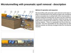
(Image: Microtunnelling with pneumatic spoil removal)
|
|
(Image: Equipment, possible arrangement of the components on the construction site and space requirements (approximately L x W = 34 x 4 m) in microtunnelling with pneumatic spoil removal - plan view (on the model of the jacking of pipes DN/ID 600, pipe length 2.0 m))
|
|
Method of operation and sequence Microtunnelling with pneumatic spoil removal on the basis of a suction plant is characterized … |
|
|
|
|
This lecture is part of the series "Trenchless 101" and serves to provide an overview of steerable trenchless new installation methods for gas, water and wastewater pipelines. |
|
|

|
|
|
|
|
|

|
|
|
|
|
|

|
|
|
|
|
|
|
|

|
|

|
|
