|
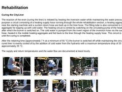
Curing the CityLiner The reaction of the resin (curing the liner) is initiated by heating the inversion water while maintaining the water pressure. For this purpose a circuit consisting of a heating supply hose running through the whole rehabilitation section, a heating aggregate positioned near the starting manhole and a suction return hose are built up in the liner hose. The filling tube is also connected to the heating aggregate for topping up … |
|
After adapting the liner in the manholes to the surface waer sewer, clearing the manholes, and successful leaktightness testing, the sealing balloon at the entrance to the rehabilitated section is removed and the surface water sewer can be taken into service again. Reusable components such as the inversion tube and the individual guide hoses are prepared for their next use. | (Image: Disassembling the inversion tower) | (Image: Disassembling the inversion … |
|
|
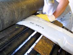
Lining of a vitrified clay sewer nominal width DN 200 with a flexible tube (DS CityLiner) impregnated with a reactive resin, forming a pipe after curing of the resin (CIPP). |
|
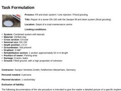
(Image: 19292 - Titelbild Dokumentation) Process: Fill and drain system / Line injection / Flood grouting Title: Repair of a sewer DN 150 with the Sanipor fill and drain system (flood grouting) Location: Depot of a road maintenance centre Limiting conditions: - System: Combined system with laterals
- Material: Vitrified clay
- Cross section: Circular
- Nominal size: DN 150
- Depth position: 2.5 m
- Groundwater: Not present
- Gradient: 3.5‰
- Rehabilitation section: …
|
|
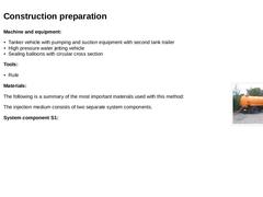
Machine and equipment: - Tanker vehicle with pumping and suction equipment with second tank trailer
- High pressure water jetting vehicle
- Sealing balloons with circular cross section
Tools: (Image: Tanker vehicle with tank trailer)
Materials: The following is a summary of the most important materials used with this method: The injection medium consists of two separate system components. System component S1: |
|
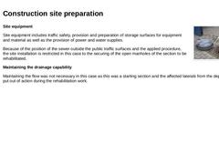
(Image: Securing the last manhole of the section to be rehabilitated) Site equipment Site equipment includes traffic safety, provision and preparation of storage surfaces for equipment and material as well as the provision of power and water supplies. Because of the position of the sewer outside the public traffic surfaces and the applied procedure, the site installation is restricted in this case to the securing of the open manholes of the section … |
|
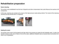
Sewer cleaning The section to be rehabilitated must be free of deposits and other contamination that could influence the reactions of the system components. In this case, cleaning was carried out by means of the high pressure water jetting method. The results of the cleaning were again checked and documented with TV inspection. | (Image: High pressure water jetting vehicle) |
(Image: High pressure water jetting vehicle - rear) |
(Image: High pressure water … |
|
|
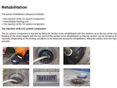
The actual rehabilitation sequence includes: - the injection of the S1 system component,
- intermediate flushing and
- the injection of the S2 system component.
The injection of the S1 system component The S1 system component is injected by filling the section to be rehabilitated with this medium up to the top of the manhole. The flooding of the sewer begins with the low point of the section to be rehabilitated so that the section can be vented at the upper … |
|
Leaktightness testing As the final hardening, according to the manufacturer's information, is only reached between 70 hours and a week, the final leaktightness testing to check the success of the rehabilitation is only carried out after this period. |
|
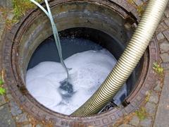
Repair of a sewer DN 150 by the Sanipor fill and drain system (flood grouting). |
|
(Image: 18460 - Titelbild Dokumentation) Process : KeraLine Title: Renovation of a DN 1200 circular cross section by partial segmental lining with KeraLine elements Place: Residential area - main road on the pavement Limiting values: - System: Combined wastewater sewer
- Material: Reinforced concrete
- Cross sectional shape: Circular cross section
- Nominal size: DN 1200
- Depth position: 3.0 - 3.5 m
- Groundwater: No
- Gradient 4.2 - 4.5 ‰
- Section length: App. 50 …
|
|
Machines and equipment - 1 Power generator at least 10 KW
- 2 Ventilators for ventilating the sewer
- 1 Air compressor
- 1 Compressed air cartridge
- 1 Compressed air angle grinder
- 1 Water level pipe and hoses
- 1 Electrical whorl agitator
- 5 Illuminating lamps
- 1 Sealing balloon
Tools - 2 type 24 mortar trowels
- 1 jointer trowel
- 1 rubber mallet
- 2 medium bedding toothed trowels
- Various buckets
Materials In the Keraline system, the connection of the dovetailed shaped … |
|
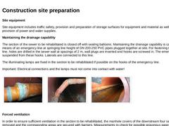
Site equipment Site equipment includes traffic safety, provision and preparation of storage surfaces for equipment and material as well as the provision of power and water supplies. Maintaining the drainage capability The section of the sewer to be rehabilitated is closed off with sealing balloons. Maintaining the drainage capability is carried out by means of an emergency line at springing line height of DN 200-250 PVC pipes plugged together at site. … |
|
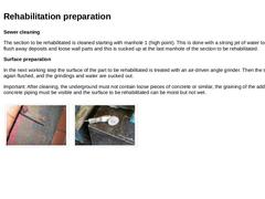
Sewer cleaning The section to be rehabilitated is cleaned starting with manhole 1 (high point). This is done with a strong jet of water to remove and flush away deposits and loose wall parts and this is sucked up at the last manhole of the section to be rehabilitated. Surface preparation In the next working step the surface of the part to be rehabilitated is treated with an air-driven angle grinder. Then the surface is once again flushed, and the grindings … |
|
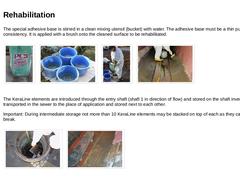
The special adhesive base is stirred in a clean mixing utensil (bucket) with water. The adhesive base must be a thin pulpy consistency. It is applied with a brush onto the cleaned surface to be rehabilitated. | (Image: Adhesive base) | (Image: Mixing utensils for stirring the adhesive base) | (Image: Mixing the adhesive base) | (Image: Adhesive base - applying the thin pulpy adhesive base) |
The KeraLine elements are introduced through the entry shaft (… |
|
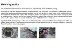
The rehabilitated stretches can be taken into service approximately 36 hours after the jointing. In this time all tools and remaining materials must be removed from the stretch. The emergency overflow line must be sealed of at its entry and an aboveground bypass pumping operation must be built up over the whole length of the rehabilitated stretch. The illumination, the electrical lines and the PVC emergency oveflow pipe are removed. The holes for … |
|
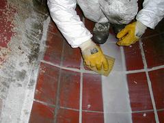
Lining of a DN 1200 sewer with prefabricated segments (vitrified clay elements), which are attached to the host pipe at the invert and cover only the invert area (partial lining with pipe segments). |
|
(Image: 18067 - Titelbild Dokumentation) Process: Grouted-in-place lining process Title: Renovating a masonry ovoid sewer DN 1000/1500 with the TROLINING® process Location: Road in an industrial area with adjoining waste dump and a builder's yard Limiting conditions: - System: Combined wastewater sewer
- Material: Masonry
- Cross section: Ovoid
- Nominal size: DN 1000/1500
- Depth position: 3.0 - 3.5 m
- Groundwater: Not present
- Gradient: 4.2 - 4.5 ‰
- Length of section: …
|
|
Machines and equipment: - 1 Fork lift truck
- 1 Capstan winch
- 1 Compressor
- 4 Uncoiling trestles
- 2 Ovoid inflatable seals
- 6 Circular inflatable sealing seals DN 150-250
- 2 Mixer units (consisting of "Minitainer", main mixer, control unit and 2 post mixers)
- 2 Extruder welding apparatuses
- 2 Angle grinders (electric, pneumatically driven)
- 1 Drilling machine with various attachments
- 1 Pad saw
Tools: - Hammer
- Putty knifes
- Rules
- Carpet and hack knives
- Pointed chisels
|
|
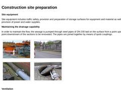
Site equipment Site equipment includes traffic safety, provision and preparation of storage surfaces for equipment and material as well as the provision of power and water supplies. Maintaining the drainage capability In order to maintain the flow, the sewage is pumped through steel pipes of DN 200 laid on the surface from a point upstream to a point downstream of the sections to be renovated. The pipes are joined together by means of quick couplings. |
|
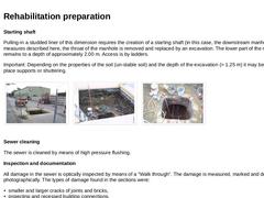
Starting shaft Pulling-in a studded liner of this dimension requires the creation of a starting shaft (in this case, the downstream manhole). For the measures described here, the throat of the manhole is removed and replaced by an excavation. The lower part of the manhole remains to a depth of approximately 2.00 m. Access is by ladders. Important: Depending on the properties of the soil (un-stable soil) and the depth of the excavation (> 1.25 m) it … |
|
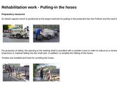
Preparatory measures An diesel capstan winch is positioned at the target manhole for pulling-in the protective foil, the Preliner and the stud hose. | (Image: Target manhole - capstan winch) |
(Image: Target manhole - capstan winch) |
For purposes of safety, the opening to the starting shaft is provided with a wooden cover in order to reduce to a minimum the danger of persons or material falling into the shaft and, in addition, to simplify the folding … |
|
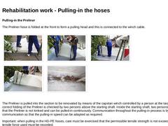
Pulling-in the Preliner The Preliner hose is folded at the front to form a pulling head and this is connected to the winch cable. | (Image: Folding the pulling head for the Preliner: step 1) | (Image: Folding the pulling head for the Preliner: step 2) | (Image: Folding the pulling head for the Preliner: step 3) | | (Image: Folding the pulling head for the Preliner: step 4) | (Image: Winch cable) |
The Preliner is pulled into the section to be renovated by means … |
|
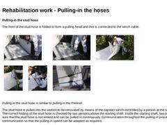
Pulling-in the stud hose The front of the stud hose is folded to form a pulling head and this is connected to the winch cable. | (Image: Folding the pulling head for the stud hose: step 1) | (Image: Folding the pulling head for the stud hose: step 2) | (Image: Folding the pulling head for the stud hose: step 3) | | (Image: Folding the pulling head for the stud hose: step 4) | (Image: Folding the pulling head for the stud hose: step 5) | (Image: Pulling head … |
|
|
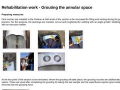
Preparing measures First nozzles are installed in the Preliner at both ends of the section to be renovated for filling and venting during the grouting process. For this purpose, the openings are marked, cut out and roughened for welding with an angle grinder. Welding is carried out with an extrusion welder. | (Image: Installing the grouting nozzles - view into the starting shaft) | (Image: Installing the grouting nozzles - marking the openings for the … |
|