|
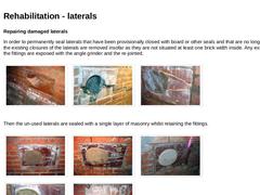
Repairing damaged laterals In order to permanently seal laterals that have been provisionally closed with board or other seals and that are no longer in use, first the existing closures of the laterals are removed insofar as they are not situated at least one brick width inside. Any existing cracks in the fittings are exposed with the angle grinder and the re-jointed. | (Image: Fittings of an lateral damaged by cracks or missing shards) |
(Image: Fittings … |
|
|
A final high-pressure flushing is carried out in order to clean the rehabilitated section before acceptance. The sewer is only optically tested for leaks, i.e. it is optically inspected for infiltrating groundwater. The last working step is the cleaning of the construction site. |
|
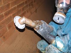
Repair of an accessible brick sewers and manholes while preserving the exposed masonry by joint rehabilitation and crack injection. |
|
(Image: 49785 - Titelbild Dokumentation) Process: Manhole rehabilitation Title: Replacement of a defective manhole top and repair of the surrounding road surface Location: Industrial area Limiting conditions: - System: Man accessible manhole with bricked manhole base and top portion of prefabricated concrete components
- Material: Concrete (part to be rehabilitated)
- Nominal size: Manhole top DN 625
- Manhole depth: 1.5 - 2.0 m
- Position of manhole: Road area…
|
|
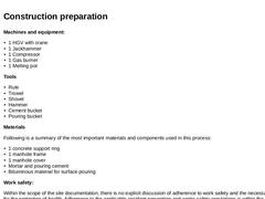
Machines and equipment: - 1 HGV with crane
- 1 Jackhammer
- 1 Compressor
- 1 Gas burner
- 1 Melting pot
Tools - Rule
- Trowel
- Shovel
- Hammer
- Cement bucket
- Pouring bucket
Materials Following is a summary of the most important materials and components used in this process: - 1 concrete support ring
- 1 manhole frame
- 1 manhole cover
- Mortar and pouring cement
- Bituminous material for surface pouring
Work safety: Within the scope of the site documentation, there is no explicit … |
|
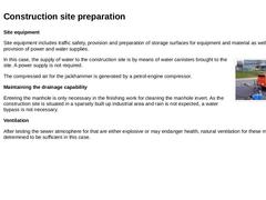
Site equipment Site equipment includes traffic safety, provision and preparation of storage surfaces for equipment and material as well as the provision of power and water supplies. (Image: Compressor) In this case, the supply of water to the construction site is by means of water canisters brought to the site. A power supply is not required. The compressed air for the jackhammer is generated by a petrol-engine compressor. Maintaining the drainage capability |
|
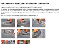
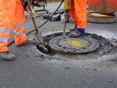
Replacement of a defective manhole top by breaking open the asphalt surface For removing the manhole top, first the road surface is chiselled up with a jackhammer around the manhole frame to a width of approximately 20 cm around the frame. The width of the working space is meant to make a professional replacement of the manhole top possible and to allow the placing of paving stones after the replacement of the top thus allowing it to be integrated … |
|
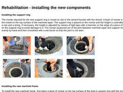
Installing the support ring The mortar required for the new support ring is mixed on site in the cement bucket with the shovel. A layer of mortar is applied with the trowel on the top surface of the manhole taper. The support ring is placed on the mortar and the height is controlled by means of a rule and a string. If necessary, the height is adjusted by means of light taps with a hammer on the edge of a piece of wood placed on the support ring to … |
|
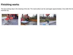
The last working step is the cleaning of the site. The road surface can be used again approximately 1 hour after the installation of the manhole top. | (Image: Loading the defective manhole top onto the truck using the crane) |
(Image: Loading the truck using the crane) |
(Image: Loading the melting equipment onto the truck using the crane) |
|
|
Replacement of a defective manhole top and repair of the surrounding road surface. |
|
(Image: 43192 - Titelbild Dokumentation) Procedure: Manhole rehabilitation Title: Replacing the manhole top in a construction road upgraded to a traffic road by means of the SS-01 steel plate system and Shark manhole frame remover Location: Industrial area Limiting values: - System: Man accessible prefabricated manhole
- Material: Concrete
- Nominal size: Manhole top DN 625
- Shaft depth: 2.0 - 2.5 m
- Position of manhole: Construction road upgraded to traffic …
|
|
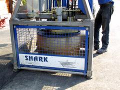
Machines and equipment - 1 "Shark" manhole frame remover placed on a truck with loading crane
- 1 High-pressure cleaning device
- 1 Drilling machine with agitator attachment
Material and help equipment: - Rule
- Trowel, jointer trowel
- Rubber faced hammer
- Paling board
- Key wrench
- Crowbar
- Sponge
- Cement bucket
- Pouring bucket
Materials: The following materials and components are used in this procedure - SS-01 steel plate system
- 2 concrete support rings
- 1 manhole frame
|
|
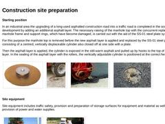
Starting position In an industrial area the upgrading of a long-used asphalted construction road into a traffic road is completed in the scope of development by adding an additional asphalt layer. The necessary raising of the manhole top with the concurrent replacement of the manhole frame and support rings, which have become damaged, is carried out with the aid of the SS-01 steel plate system. For this purpose the manhole top is removed before the … |
|
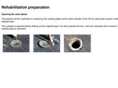
Opening the steel plates The position of the manholes is marked by the sealing plates of the steel cylinder of the SS-01 steel plate system visible in the asphalt layer. The cylinder is opened before drilling out the asphalt layer. For this purpose the hex. nuts are loosened with a wrench and the sealing plate is removed. | (Image: Opening the cylinder of the SS-01 steel plate system) |
(Image: Opening the cylinder of the SS-01 steel plate system) |
(Image: … |
|
|
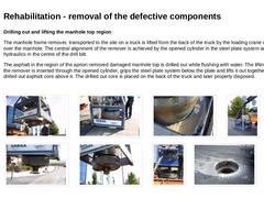
Drilling out and lifting the manhole top region The manhole frame remover, transported to the site on a truck is lifted from the back of the truck by the loading crane and positioned over the manhole. The central alignment of the remover is achieved by the opened cylinder in the steel plate system and the lifting hydraulics in the centre of the drill bitt. The asphalt in the region of the apriori removed damaged manhole top is drilled out while flushing … |
|
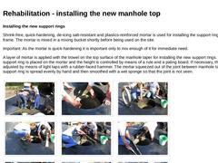
Installing the new support rings Shrink-free, quick-hardening, de-icing salt-resistant and plastics-reinforced mortar is used for installing the support ring and manhole frame. The mortar is mixed in a mixing bucket shortly before being used on the site. Important: As the mortar is quick-hardening it is important only to mix enough of it for immediate need. A layer of mortar is applied with the trowel on the top surface of the manhole taper for installing … |
|
After installing the new manhole frame, the manhole invert is cleaned manually of any asphalt or mortar remains that may have dropped into it during the repair work. The site is cleared. The road surface can be used again approximately 1 hour after the installation of the manhole top. |
|
Repair of manhole top by replacement by means of steel plate system SS-01 and Shark manhole frame remover machine. |
|
(Image: 19111 - Titelbild Dokumentation) Process: KM-Inliner Title: Renovation of a vitrified clay sewer DN 250 to DN 350 with the KM-Inliner method Location: Residential district within the road pavement and in front gardens Limiting conditions: - System: Sewer with 3 laterals
- Material: Vitrified clay
- Cross section: Circular profile
- Nominal size: DN 250
- Depth position: 2,0 - 3,0 m
- Groundwater: Not present
- Gradient: ca. 4.0 ‰
- Rehabilitation section: …
|
|
Use of machines and equipment The technical equipment of the KM-Inliner team for this particular case consists of:: - 1 tensioning machine
with container structure with rest room and workshop space - 1 tensioning machine
with heating plant (250 KW to 1.5 MW), emergency generator (30 KW/ 380V), compressor - 1 refrigerated container vehicle
- 1 inspection vehicle
with TV swivel-head camera, drilling and milling robot - 1 high pressure flushing vehicle
- 1 accompanying …
|
|
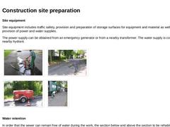
Site equipment Site equipment includes traffic safety, provision and preparation of storage surfaces for equipment and material as well as the provision of power and water supplies. The power supply can be obtained from an emergency generator or from a nearby transformer. The water supply is connected to a nearby hydrant. | (Image: Water supply from a hydrant) |
(Image: Water supply from a hydrant) |
| (Image: emergency power supply) |
(Image: Traffic safety … |
|
|
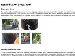
Cleaning the Sewer The section to be rehabilitated must be free from deposits and other flow obstacles. In this case it is cleaned by means of the high-pressure jetting method. If obstacles are found which cannot be removed by this method of cleaning then they are removed using a sewer milling robot. The results of the cleaning are rechecked by TV inspection and documented before the start of rehabilitation. | (Image: Positioning the high pressure … |
|
|
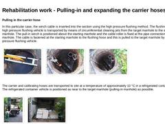
Pulling in the carrier hose In this particular case, the winch cable is inserted into the section using the high pressure flushing method. The flushing hose of the high pressure flushing vehicle is transported by means of circumferential cleaning jets from the target manhole to the starting manhole. The pull-in winch is positioned above the starting manhole and the cable roller is fixed at the pipe connection in the manhole. The cable is fastened … |
|
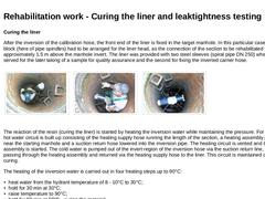
Curing the liner After the inversion of the calibration hose, the front end of the liner is fixed in the target manhole. In this particular case, a bearing block (here of pipe spindles) had to be arranged for the liner head, as the connection of the section to be rehabilitated was approximately 1.5 m above the manhole invert. The liner was provided with two steel sleeves (spiral pipe DN 250) whereby the first served for the later taking of a sample … |
|
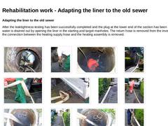
Adapting the liner to the old sewer After the leaktightness testing has been successfully completed and the plug at the lower end of the section has been removed, the water is drained out by opening the liner in the starting and target manholes. The return hose is removed from the inversion pipe and the connection between the heating supply hose and the heating assembly is removed. | | | | | | | | (Image: Pulling out the sealing element) | (Image: Pulling … |
|