|

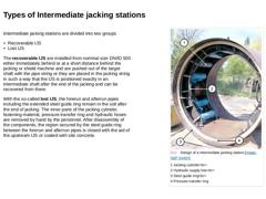
Intermediate jacking stations are divided into two groups The recoverable IJS are installed from nominal size DN/ID 500 either immediately behind or at a short distance behind the jacking or shield machine and are pushed out of the target shaft with the pipe string or they are placed in the jacking string in such a way that the IJS is positioned exactly in an intermediate shaft after the end of the jacking and can be recovered … |
|
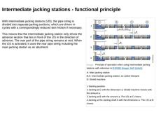
With intermediate jacking stations (IJS), the pipe string is divided into separate jacking sections, which are driven in cycles with a correspondingly reduced skin friction if necessary. This means that the intermediate jacking station only drives the advance section that lies in front of the IJS in the direction of advance. The rear part of the pipe string remains at rest. When the IJS is activated, it uses the rear pipe string including the main … |

|
(Video: Arrangement and development of the forces of intermediate jacking stations during pipe jacking) |

|
|
(Image: Attention!)
The operation of the IJS is carried out from the steering desk. Only one hydraulic supply line is required for each station. |
For long jacking distances the single intermediate jacking stations are either supplied |

|
|
(Image: Attention!)
When planning intermediate jacking stations, care must be taken of the following facts: -
the positions of the intermediate jacking stations within the pipe string are defined with reference to the planned intermediate shafts or shaft constructions
-
all intermediate jacking stations that are used for a jacking project are identical in their design and performance (same number of jacking cylinders per intermediate jacking station / …
|
|

|
|
(Image: Pros and cons)
When using intermediate jacking stations, the following disadvantages must be expected: -
increase in costs due to the installation and the storage of all necessary system parts as well as the activation
-
reduction of the jacking performance
|
|

|

|
|
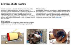
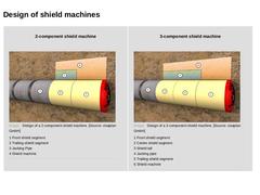
A shield machine is a steerable sheeting construction, in the protection of which the soil / rock on the working face is excavated manually, mechanically or hydraulically. It consists of at least two flexible connected steel pipe pieces, the front shield segment and the trailing shield segment, which is supported by the jacking pipe string. A distinction is made here between open and closed shields or shields with partial and full face excavation. |
|
|
(Image: Attention!)
The feature of shield machines, also called shields, for pipe jacking, is that the thrust jacks (jacking cylinders) are situated not in the shield machine, but in the (main) jacking station or in the first intermediate jacking station. |
|
The soil or rock material can be excavated at the working face with the following methods: |
|
|

|
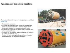
The duties of the shield machine in pipe jacking are as follows [Scher77a]: -
To protect the personnel,
-
To create the necessary cavity so that the following pipe string can be pressed in with a minimum degree of soil deformation and with the lowest possible skin friction,
-
To protect the cavity until the jacking pipes can finally carry all the loads and forces,
-
To secure the working face against collapsing soil and rock as well as groundwater, …
|
|
|
|
2-component shield machine (Image: Design of a 2-component shield machine) |
3-component shield machine (Image: Design of a 3-component shield machine) |
|

|

(Image: Overview of shield machine types) |
|

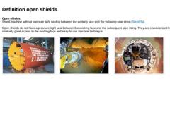
Open shields:
Shield machine without pressure tight sealing between the working face and the following pipe string [Stein05a]. Open shields do not have a pressure-tight seal between the working face and the subsequent pipe string. They are characterized by relatively good access to the working face and easy-to-use machine technique. (Image: Hand shields - Overall view of a hand shield (external diameter 2098 mm) [FI-Nishi]) (Image: Open shield) (Image: … |

|

|
Shield machines with partial excavation feature an open (SM-T1 or SM-T2) or closed shield (SM-T3 or SMT4) and partial loosening of the soil or material at the working face.
Shield machines with partial excavation of the working face are grouped according to the method of excavation into: -
Shield machines with partial excavation by hand (hand shields)
-
Shield machines with mechanical partial excavation
-
Shield machines with hydraulic partial excavation
|
|
|
|
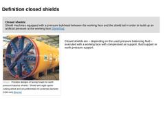
Closed shields:
Shield machines equipped with a pressure bulkhead between the working face and the shield tail in order to build up an artificial pressure at the working face [Stein05a]. |
(Image: Possible designs of boring heads for earth pressure balance shields - Shield with eight-spoke cutting wheel and circumferential rim (external diameter 3100 mm) [Breme])
Closed shields are – depending on the used pressure balancing fluid – executed with … |
|
|

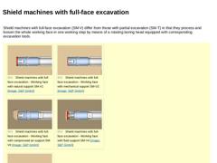
| Shield machines with full-face excavation (SM-V) differ from those with partial excavation (SM-T) in that they process and loosen the whole working face in one working step by means of a rotating boring head equipped with corresponding excavation tools. | | (Image: Shield machines with full-face excavation - Working face with natural support SM-V1) | (Image: Shield machines with full-face excavation - Working face with mechanical support SM-V2) | | (Image: … |
|
|

|

|
|
|
(Image: Attention!)
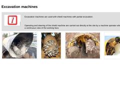
Excavation machines are used with shield machines with partial excavation.
Operating and steering of the shield machine are carried out directly at the site by a machine operator who has a continuous view of the working face. |
|
(Image: Shield machine with fixed installed boom cutting machine - With axial cutting head) |
(Image: Axial cutter head of the boom cutting machine equipped with round shank cutter bits) |
(Image: Principles … |
|
|

|

|

|

|
|
|

|
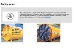
(Image: Three-spoke rim cutting wheel with scraper teeth (standard bore head) [FI-Rasa]) The cutting wheel is a largely openly designed drilling head that is not used for the mechanical support of the working face. Their advantages lie with the low coverage and thus the good accessibility of the working face when needed. A distinction is made between the spoke and the rim cutting wheel [Maidl98]. |
|
(Image: Possible designs of boring heads for earth … |
|
|
|
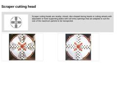
(Image: Scraper cutting head with pick bits and scraper teeth (standard bore head) [FI-Rasa])
Scraper cutting heads are nearby, closed, disc-shaped boring heads or cutting wheels with adjustable or fixed supporting plates with soil entry openings that are adapted to suit the size of the maximum particle to be transported. |
|
(Image: Open shield machine with scraper cutting head and mechanical support of the working face - Variably adjustable soil … |
|
|
|
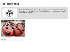
(Image: Rock cutting head with disc cutters and TCI insert roller cutter for hard rock [FI-Rasa])
Rock cutting heads consist of almost closed, disc-shaped basic constructions with usual slot-shaped entry openings (removal slots) and are flat with a rounded periphery, slightly coned or almost convex. |
|
(Image: Rock cutting head of a shield with fluid support of the type AVN 1500 for jacking in rock - view) |
|

|

|