|
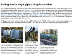
This variant of the pulling-in process is used where only limited space is available such as in inner-urban regions and river culverts or inverted siphons with steep banks (see (Drinking water supply line DN 400 in the moorlands between De Meern und Harmelen)). In this case, pipes or pipe strings with restrained plug-in joints (see Volume 1, Chapter 13 [HDD-1]), for instance, ductile cast iron pipes (see (Ductile cast iron pipes)), are connected … |
|
The following working steps are necessary for carrying out the method (Figure 3a, Figure 3b, Figure 3c) [HDD-12] [HDD-17] [HDD-18]: -
pilot bore,
-
reaming(s) and
-
pulling-in.
(Image: Working steps in HDD – Pilot bore) (Image: Working steps in HDD – Reaming) (Image: Working steps in HDD – Pulling-in) Phase 1: Pilot bore After determining the line and gradient for the pipe(s) to be installed, which – because of the steerable drill head – can occupy a wide … |
|
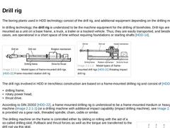
The boring plants used in HDD technology consist of the drill rig, and additional equipment depending on the drilling method. In drilling technology, the drill rig is understood to be the machine equipment for the drilling of boreholes. Drill rigs are usually mounted as a unit on a base frame, a truck, a trailer or a tracked vehicle. Thus, they are easily transported, and besides exceptional cases, are operational in a short space of time without … |
|
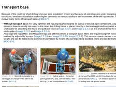
Because of the relatively short drilling times per pipe installation project and because of operation also under complicated site conditions, trenchless installation makes higher demands on transportability or self-movement of the drill rigs on site. This can involve many forms of transport bases [HDD-17]: -
Without transport base: For very light Mini drill rigs especially designed for lateral or service pipe connections, a special transport base is …
|
|
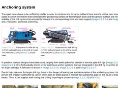
Transport bases have to be sufficiently stable in order to introduce the thrust or pullback force into the drill or pipe string. In most cases in which the friction forces between the positioning surface of the transport base and the ground surface are insufficient, the stability of the drill rig must be ensured by means of a corresponding front and rear support (Figure 13 a and 13b) and, if required, additional anchoring. (Image: Equipment of a Midi … |

|
Because of the relatively short drilling times per pipe installation project and because of operation also under complicated site conditions, trenchless installation makes higher demands on transportability or self-movement of the drill rigs on site. This can involve many forms of transport bases [HDD-17]: -
Without transport base: For very light Mini drill rigs especially designed for lateral or service pipe connections, a special transport base is …
|
|
The components of the drive assembly, i.e. -
thrust drive,
-
rotary power head,
-
adjustment of the drilling frame’s inclination,
-
crushers,
-
movement of the crushers,
-
crane,
-
drill rod change system,
-
introduction of the anchor for fixing the soil plate,
-
chassis and
-
flushing pumps
are operated via hydraulic power packs in the form of hydraulic cylinders and hydraulic motors (axial piston- , radial piston- or gear wheel motors). They are energized … |
|
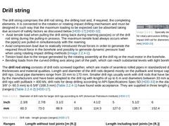
(Image: Specially designed drill rod for rotary-percussive drilling (TwinDrive-impact drill rod for diameters 48 mm to 82 mm))The drill string comprises the drill rod string, the drilling tool and, if required, the completing elements. It is connected to the rotation or rotating impact drilling mechanism and must be designed in such way that the maximum loading to be expected can be absorbed taking due account of safety factors as discussed below [… |
|
Concerning the drilling tools, the following are differentiated in HDD depending on the working steps: -
drilling tools for pilot boring,
-
drilling tools for reaming(s),
-
drilling tools for borehole calibration,
-
drilling tools for smoothing the borehole.
|
|
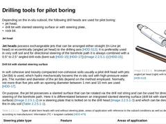
(Image: In-Line-jet head (left) and angled jet head (right) with bent sub)Depending on the in-situ subsoil, the following drill heads are used for pilot boring: -
jet head,
-
drill bit with slanted steering surface or with steering plate,
-
rock bit.
Jet head Jet heads possess exchangeable jets that can be arranged either straight (In-Line jet head) or eccentrically (angled jet head) to the drilling axis [HDD-513]. It is preferably used in very soft soil … |
|
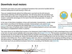
(Image: Helical gear motors according to the Moineau principle)Downhole mud motors are used in geological formations that cannot be handled with the common drilling tools for pilot boring in loose soil. They are installed directly behind the drilling tool or are built into the drill string by intermediate switching of drill string elements. The drill string above the downhole mud motor must take up the return moment and in this case does not need … |
|
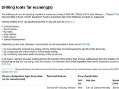
The drilling tool used for reaming is called a reamer according to DIN EN 12889 [HDD-9] (see Volume 1, Chapter 7 [HDD-1]) and also borehole or back reamer, expansion head or expansion tool in the technical literature or in practice. Various models are in use depending on the in-situ soil such as [HDD-17]: -
conical reamer,
-
barrel reamer,
-
fly cutter,
-
wing reamer,
-
hole opener,
-
special developments.
Depending on the type of reamer, the borehole can … |
|
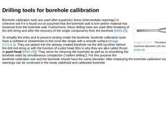
(Image: Thrust/push head for borehole diameters 135 mm and 190 mm)Borehole calibration tools are used after expansion bores (intermediate reamings) in cohesive soil if it is found out or assumed that the borehole wall is torn and/or material has loosened from the borehole wall. Furthermore, these drilling tools are used after breaking of the drill string and after the recovery of the single components from the borehole [HDD-23]. To simplify the entry … |
|
For large borehole diameters and drilling in friable, non-stable soil, it can be necessary to carry out a socalled smoothing- or cleaning-run [HDD-58] (also called “check-Trip“ [HDD-94]) (cf. also (Calculations for the state of construction) Tip, (“Meeting-in-the-Middle“ technique) and (Crossing the Elbe River near St. Margarethen)). For this purpose a conical reamer without tooling with a final diameter of the borehole that is to be expanded is … |
|
Concerning the drilling tools, the following are differentiated in HDD depending on the working steps: -
drilling tools for pilot boring,
-
drilling tools for reaming(s),
-
drilling tools for borehole calibration,
-
drilling tools for smoothing the borehole.
|
|
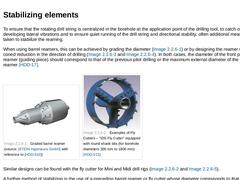
To ensure that the rotating drill string is centralized in the borehole at the application point of the drilling tool, to catch or prevent any developing lateral vibrations and to ensure quiet running of the drill string and directional stability, often additional measures are taken to stabilize the reaming. When using barrel reamers, this can be achieved by grading the diameter (Figure 47) or by designing the reamer with a strong coned reduction … |
|
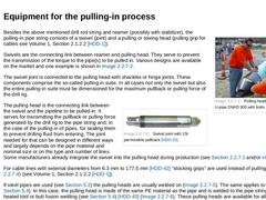
(Image: Pulling head fixed to a PVC-U-pipe DN/ID 300 with bolts)Besides the above mentioned drill rod string and reamer (possibly with stabilizer), the pulling-in pipe string consists of a swivel (joint) and a pulling or towing head (pulling grip for cables see Volume 1, Section 2.1.2.2 [HDD-1]). Swivels are the connecting link between reamer and pulling head. They serve to prevent the transmission of the torque to the pipe(s) to be pulled in. Various … |
|
(Image: Expanding pulling heads, partially in connection with sealing installations – Structure and view (without sealing) of the pulling-in suite)As shown in Figure 53 a, the connection between the drill rod string and pipe string during pulling-in usually consists of reamer, swivel and pulling head. Normally this construction is relatively long and sometimes has large play towards the sides unlike the axis of the pipe to be pulled-in. If the entry … |
|
(Image: Pulling head fixed to a PVC-U-pipe DN/ID 300 with bolts)Besides the above mentioned drill rod string and reamer (possibly with stabilizer), the pulling-in pipe string consists of a swivel (joint) and a pulling or towing head (pulling grip for cables see Volume 1, Section 2.1.2.2 [HDD-1]). Swivels are the connecting link between reamer and pulling head. They serve to prevent the transmission of the torque to the pipe(s) to be pulled in. Various … |
|
(Image: Semi automatic drill rod change system with steerable drill rod gripper – Placing the drill rod into the drilling frame)A particular feature in the development of HDD-methods is the widespread mechanisation and automating of the installation and removal of the drill rods with the intention of reducing the time spent, the amount of work involved and the number of drilling personnel. In order to install a new drill rod, the already jacked drill … |
|
Depending on the construction task, various kinds of additional equipment are available to simplify and monitor the pulling-in process in practice, such as -
multiple clamps for group installation,
-
jacking station to support the pulling-in (or pushing-in) process with large steel pipes (“Pipe Thruster“),
-
measuring systems.
|
|
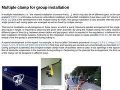
In multiple installations, i.e. “the shared installation of several lines [...], which may also be of different types, in the same line and gradient“ [HDD-1], until today exclusively unbundled installation and bundled installation have been used (cf. Volume 1, Section 2.2 [HDD-1]). Due to the development of the multiple clamp for HDD, now group installation is also possible with this technology. Here single product and casing pipes are arranged as … |
|
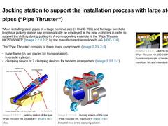
(Image: Jacking station of the type "Pipe-Thruster HK 250/500PT" – Functional principle of tandem)When installing steel pipes of a large nominal size (> DN/ID 700) and for large borehole lengths a jacking station can systematically be employed at the pipe exit point in order to support the drill rig during pulling-in. A corresponding example is the “Pipe Thruster HK250/500PT“ (Figure 65 a) by the manufacturer Herrenknecht AG [HDD-174]. The “Pipe Thruster“ … |
|
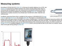
(Image: Tensile load measuring system GRUNDOLOG III – View)According to DVGW-GW 321 [HDD-15], in Germany for plastic pipelines (e.g. of PE, see (PE-pipes)) basically the pullback between the reamer and the pulling head, which is connected with the pipeline, are to be measured and recorded for tracing the pulling-in process and to prevent the pipeline from possible overload [HDD-51]. In practice, this requirement to quality assurance has already been … |
|
Depending on the construction task, various kinds of additional equipment are available to simplify and monitor the pulling-in process in practice, such as -
multiple clamps for group installation,
-
jacking station to support the pulling-in (or pushing-in) process with large steel pipes (“Pipe Thruster“),
-
measuring systems.
|