
|

|
|

|
(Image: Unmanned techniques)
|
|
(Image: Non-steerable techniques)
|
|
(Image: Soil removal techniques)
|
|
In soil removal techniques, steel pipes are jacked either dynamically or statically from a starting shaft to a target shaft whereby the soil or rock material loosened by the jacking is transported away either continuously, in intervals or after the boring. The waste material is typically called spoil or mud [Arnol93]. In all the following soil removal … |
|
|

|
(Image: Soil removal technique - pipe ramming with open pipe front)
|
|
(Image: Soil removal technique - uncased boring (free boring))
|
|
(Image: Soil removal technique - auger boring)
|
|
The soil removal techniques include the following processes: - Pipe ramming with open pipe front
- Uncased auger boring
- Auger boring
- Hammer drilling
- Horizontal jacking with reamer .
| |
(Image: Soil removal technique - hammer drilling)
|
(Image: Soil removal techique - … |
|
|
|

| (Image: Pipe ramming with open pipe front - site situation [FI-Steina])
|
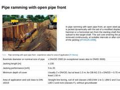
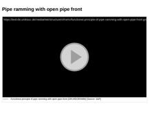
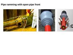
In pipe ramming with open pipe front, an open steel pipe string is jacked dynamically with the aid of a modified displacement hammer or a horizontal ram from the starting shaft through the subsoil to the target shaft. The soil core entering the pipe is removed continuously, at suitable intervals or after completion of the jacking [ATVA125:1996]. | (Table: Pipe ramming with open … |
|
|

(Video: Functional principle of pipe ramming with open pipe front (GRUNDORAMM)) |
|

|
(Image: Horizontal ram with soil removal adaptor and impact segment installed in the starting shaft)
|
(Image: Horizontal ram with soil removal adaptor and impact cone)
|
(Image: Horizontal ram with soil removal adaptor, impact cone and carriage)
|
|
|

|

| (Image: Soil removal technique - uncased boring (free boring))
|
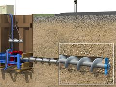
In uncased auger boring, the subsoil is bored through in a rotating manner by means of an auger bore string and the loosened spoil is conveyed from the uncased borehole to the starting shaft. The uncased auger machine is based on the auger boring without casing [Arnol93] and presents the simplest method variant of all boring techniques based on the spoil removal by rotating and helically … |
|
|

| (Image: Soil removal technique - auger boring)
|
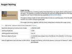
Auger boring:
Soil is excavated by a rotating cutting head attached to an auger which continuously removes the spoil. The pipeline is pushed simultaneously with and independently from the auger. The equipment can have limited steering capability [DINEN12889:2000]. The pipe is always made of steel and besides its task as a jacking pipe; it has the additional function of a screw conveyor guide pipe. The … |
|
|

| (Image: One-stage jacking of steel pipe)
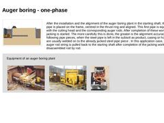
After the installation and the alignment of the auger boring plant in the starting shaft, the first pipe is placed on the frame, centred in the thrust ring and aligned. This first pipe is equipped with the cutting head and the corresponding auger rods. After completion of these works, the jacking is started. The more carefully this is done, the greater is the alignment accuracy. All the following pipe pieces, … |
|
|

|
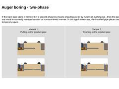
If the steel pipe string is removed in a second phase by means of pulling out or by means of pushing out , then the pipe piece are made in an easily released tensile- or non-restrained manner. In this application case, the installed pipe pieces are called temporary pipes. | Variant 1
Pulling-in the product pipe |
(Image: Auger boring - working sequence in two-phase jacking with reference to [FI-Lanci] [FI-Krupp] [Image: S&P GmbH] - Phase 1: Jacking the … |
|
|
|

| (Image: Soil removal technique - hammer drilling)
|
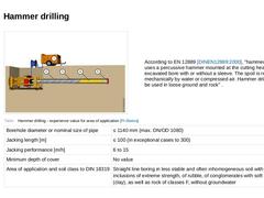
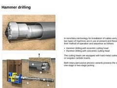
According to EN 12889 [DINEN12889:2000], "hammer drilling uses a percussive hammer mounted at the cutting head in the excavated bore with or without a sleeve. The spoil is removed mechanically by water or compressed air. Hammer drilling may be used in loose ground and rock" . | (Table: Hammer drilling - experience value for area of application [FI-Steina]) |
|
|

|
(Image: Down-the-hole hammer with eccentric cutting head and reamer and steel pipe with reference to [Arnol93] [Image: S&P GmbH] - Principle of operation)
|
|
(Image: SST method with reference to [FI-Asanu] [Image: S&P GmbH] - Overview sketch)
|
|
In trenchless technology for installation of cables and pipes, two types of machines are in use at present and these differ in their method of operation and sequence as follows: - Hammer drilling with eccentric …
|
|

|

|
|

This lecture is part of the series "Trenchless 101" and serves to provide an overview of non-steerable trenchless new installation methods for gas, water and wastewater pipelines. |
|
Underground pipelines and utilities are predominantly installed by using the traditional open-cut method (i.e., cut and fill): a trench is dug, the lines are installed by constructing proper embankment or sheeting or using a trench box, and the trench is filled afterwards. In the face of the numerous challenges (e.g., urbanization, densely populated areas) as well as growing environmental consciousness, it is important to consider trenchless technology … |
|
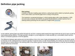
(Image: Manned techniques) (Image: Steerable techniques) Pipe jacking:
A system of directly installing pipes behind a cutting head and/or shield, by hydraulic jacking from a drive shaft, such that the pipes form a string in the ground.
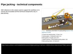
The manned or unmanned technique, in which jacking pipes with a clear diameter ≥ 1200 mm (not to be confused with DN/ID) are jacked directly behind a shield machine from a starting shaft by pressing into the subsoil … |
|

|

|

|
|
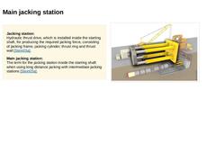
Jacking station:
Hydraulic thrust drive, which is installed inside the starting shaft, for producing the required jacking force, consisting of jacking frame, jacking cylinder, thrust ring and thrust wall [Stein05a]. Main jacking station:
The term for the jacking station inside the starting shaft when using long distance jacking with intermediate jacking stations [Stein05a]. (Image: Technical components in pipe jacking - main jacking station) |
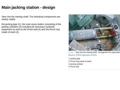
|

|
|
|
(Image: Attention!)
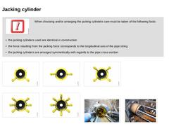
When choosing and/or arranging the jacking cylinders care must be taken of the following facts: -
the jacking cylinders used are identical in construction
-
the force resulting from the jacking force corresponds to the longitudinal axis of the pipe string
-
the jacking cylinders are arranged symmetrically with regards to the pipe cross-section
|
|
|
|
(Image: Use of two jacking cylinders combined with a steel pressure ring for four … |
|
|
|

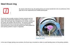
By means of the thrust ring, the jacking forces are evenly transferred to the circumference of the pipe face of the respectively last installed jacking pipe The thrust ring normally consists of torsion-resistant and low-deformation unperforated weldments of steel plates. In most cases, the thrust pipe ring is designed as an annular, reinforced box girder with parallel, flat front faces. The jacking cylinders that transfer the forces … |

|

|
|

Intermediate jacking station:
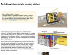
Cylindric steel skin integrated between interjack forerun and afterrun pipe with jacking cylinders for reducing the jacking forces when carrying out jackings of large length or/and in rock [Stein05a] (also called interjacks). (Image: Technical components in pipe jacking - intermediate jacking station) Intermediate jacking stations (IJS) also called interjack (stations), consist of several jacking cylinders that are installed … |
|

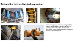
(Image: Intermediate jacking station - view of the jacking cylinders) (Image: Design and arrangement of intermediate jacking stations - Detail view of the jacking cylinders) (Image: Intermediate jacking station before installation of the cylinders) (Image: Built-in and activated cylinders of an intermediate jacking station) (Image: Intermediate jacking station before the installation in the pipeline tract)Intermediate jacking stations are integrated … |