|

|
|

|
|

|
|

|

|

|
|
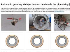
The number and arrangement of the injection nozzles per lubrication station are usually constant. In addition to the control of all existing valves, it is possible to change the positions of the injection nozzles in the cross-section at successive lubrication stations in order to realize an almost uniformly distributed lubricant injection at the pipe circumference [Schoesser2013]. (Image: Detail - Injection nozzle) (Image: Arrangement of injection … |
|

The number and arrangement of the injection nozzles per lubrication station are usually constant. In addition to the control of all existing valves, it is possible to change the positions of the injection nozzles in the cross-section at successive lubrication stations in order to realize an almost uniformly distributed lubricant injection at the pipe circumference [Schoesser2013]. (Image: Detail - Injection nozzle) (Image: Arrangement of injection … |
|

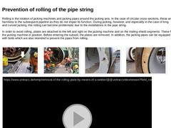
Rolling is the rotation of jacking machines and jacking pipes around the jacking axis. In the case of circular cross-sections, these are harmless to the subsequent pipeline as they do not impair its function. During jacking, however, and especially in the case of long and curved jacking, this rolling can become problematic due to the installations in the pipe string. In order to avoid rolling, plates are attached to the left and right on the jacking … |
|

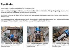
A pipe brake is used to fix the pipe string in the starting pit. In the event of pressing groundwater, use of a hydraulic joint, the inclination of the jacking string, etc., the pipe string may move backward into the starting pit when the pipe is changed. As the pipe string can no longer be fixed by the main jacking station during pipe replacement, a pipe brake takes over the securing of the pipe string. Pipe brakes are usually pneumatic brakes whose … |
|

|
|
Today, supply and discharge lines are still predominantly installed by using the open-cut method: a trench is dug, the lines are installed. Under the protection of an embankment or sheeting and the trench is filled afterwards. In the face of the numerous disadvantages as well as the citizens' growing environmental consciousness in the future it is urgently necessary to take trenchless technology into account much stronger than until today as an alternative … |
|

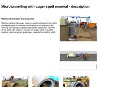
Method of operation and sequence Microtunnelling with auger spoil removal is characterized by the jacking of pipes in soils with simultaneous excavation of the working face using a cutting head and by continuous removal of the spoil with a spiral conveyor or auger, which is guided inside a spiral conveyor guide pipe, towards the starting shaft. (Image: Technical components for microtunnelling with auger spoil removal in single phase jacking) (Image: … |
|
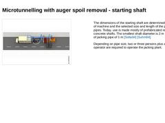
(Image: Equipment, possible arrangement of the components on the construction site and space requirement (approximately L × W = 22.0 × 4.0 m) in microtunnelling with auger spoil removal - top view (on the model of the jacking of pipes DN/ID 600, pipe length 2.0 m)) The dimensions of the starting shaft are determined by the type of machine and the selected size and length of the jacking pipes. Today, use is made mostly of prefabricated reinforced concrete … |
|
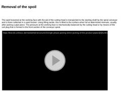
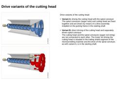
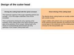
The spoil loosened at the working face with the aid of the cutting head is transported to the starting shaft by the spiral conveyor and is there collected in a spoil bucket. Using lifting tackle, this is lifted to the surface when full at determined intervals, usually after jacking a pipe piece. The pressure at the working face is mechanically balanced by the cutting head or by means of the soil plug that is formed in the front section of the conveyor … |
|
|

|
|
|
|

|
|
|

|
|

|

Possible measures for the application in groundwater-bearing soil: -
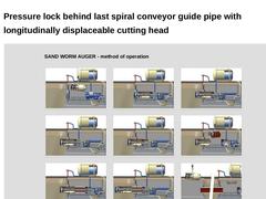
Combination of a rotary vane lock at the end of the spiral conveyor or a rotating feed apparatus with a longitudinally displaceable cutting head
-
Arrangement of a ring-shaped inflatable elastomeric sealing system ("compressed air valve") in the spiral conveyor guide pipe
-
Combination of a compressed air valve in the spiral conveyor guide pipe with a longitudinally displaceable cutting …
|
|
|
|
|
|

|
|

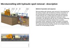
(Image: Microtunnelling with hydraulic spoil removal in single phase jacking) (Image: Basic equipment, possible arrangement components on the construction site and space requirements (ca. L × B = 35 × 4 m) for microtunnelling with hydraulic spoil removal - plan view (on the model of the jacking of pipes DN/ID 600, pipe length 2.0 m)) Method of operation and sequence Microtunnelling with hydraulic spoil removal is characterized by the jacking of pipes … |
|
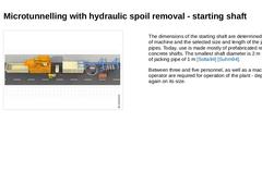
(Image: Basic equipment, possible arrangement components on the construction site and space requirements (ca. L × B = 35 × 4 m) for microtunnelling with hydraulic spoil removal - plan view (on the model of the jacking of pipes DN/ID 600, pipe length 2.0 m)) The dimensions of the starting shaft are determined by the type of machine and the selected size and length of the jacking pipes. Today, use is made mostly of prefabricated reinforced concrete … |