|
When dimensioning the individual lining elements, account must be taken of the final condition as well as all construction phases of their installation and possible removal [Weiße75b]. The respective permissible stresses of the individual lining elements must be taken from the "EAB - 100" [EAB100] and DIN 4124 [DIN4124:2002]. Particular conditions must be met in the manufacture of types of linings that can be used universally and are re-usable. They … |
|
The earth structural stability analysis includes: - Assessment against hydraulic ground failure during construction of the shaft before the introduction of the base for cut off groundwater
- Assessment of buoyancy security after the introduction of base for cut off groundwater
- Assessment of the earth bearing for introducing the jacking force into the subsoil behind the installed abutment.
The first two assessments that only apply to the shafts reaching … |
|
The jacking forces that alternate between zero and the greatest load are transferred by the jacking cylinders through the abutments either, in unlined shafts directly or, for lined shafts indirectly into the lining wall and through its inherent stiffness into the subsoil. The soil stresses are the result of the size of the jacking force, the shaft depth, the soil properties and the geometric dimensions of the abutment. In the interest of a better … |
|
|
|
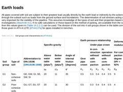
All pipes covered with soil are subject to their greatest load usually directly by the earth load or indirectly by the actions transferred through the subsoil such as loads from the ground surface and foundations. The determination of soil stresses acting on the pipe is very important for the stability of the pipeline. This assumes knowledge of the types of soil and their properties based on soil investigations (Abschnitt 4.1). If no safe calculations … |
|
Large area loads which are always there during jacking (for instance embankments) can usually be taken as a correspondingly larger soil covering, although without taking into consideration the silo effect for the respective earth load portion [ATVA161]. According to ATV-A 161E [ATVA161] when jacking under bodies of water, κ = 1 must always be assumed for safety reasons. |
|
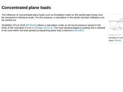
(Image: Pressure spreading of concentrated plane loads [Trian00]) The influence of concentrated plane loads such as foundation loads on the jacked pipe string must be assessed in individual cases. For this purpose, a calculation in the elastic isotropic halfspace can be carried out. Simplified, ATV-A 161E [ATVA161] allows a calculation under an all-round pressure spread in the limits of the inclination 2:1 to 1:1 (Bild 14.1.4). The most disadvantageous … |
|
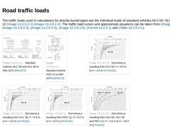
The traffic loads used in calculations for directly buried pipes are the individual loads of standard vehicles HLC 60, HLC 30 and HGV 12 (Bild 14.1.5.1) (Bild 14.1.5.1). The traffic load curves and approximate equations can be taken from Bild 14.1.5.1, Bild 14.1.5.1, Bild 14.1.5.1, Bild 14.1.5.1, Formel 14.1.5.1 and Tabelle 14.1.5.1. | (Image: Standard vehicles HLC 30 and HLC 60 to DIN 1072 [DIN1072]) |
(Image: Standard vehicle HGV 12 to DIN 1072 [DIN1072]) |
|
|
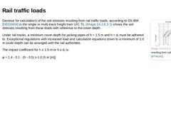
(Image: Soil stresses resulting from rail traffic loads [ATVA161]) Decisive for calculations of the soil stresses resulting from rail traffic loads, according to DS 804 [DEDS804] is the single or multi-track freight train UIC 71. Bild 14.1.5.2 shows the soil stresses resulting from these loads with reference to the cover depth. Under rail tracks, a minimum cover depth for jacking pipes of h = 1.5 m and h = di must be adhered to. Exceptional regulations … |
|
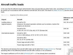
In the case that the affected airport administration does not prescribe any other loads, then, according to [ATVA161], calculations can be carried out in accordance with the reference aircraft DAC 90 to DAC 750 shown in Tabelle 14.1.5.3 and the corresponding loads. (Table: Assignment of the reference aircraft) (Image: Soil stresses resulting from aircraft traffic loads [ATVA161])
The decisive soil stresses from aircraft traffic loads can be taken from |
|
|
|
Besides the already mentioned earth and traffic loads, the following loads lateral to the pipe axis must also be considered (Tabelle 14.1) : - Dead weight
The dead weight of the pipes are calculated from the wall thickness and the weight per unit volume of the pipe material.
- Water filling up to the pipe crown
The water filling must be calculated as being up to the pipe crown. Part fillings are not considered.
- Internal overpressure or vacuum
The internal …
|
|
|
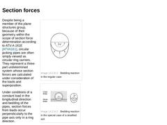
(Image: Bedding reaction in the regular case)
|
|
(Image: Bedding reaction in the special case of a stratified soil)
|
|
(Table: Determination of section forces perpendicular to the pipe axis [ATVA161]) |
Despite being a member of the plane structures group, because of their geometry within the scope of section force determination according to ATV-A 161E [ATVA161], circular jacking pipes are often simply viewed as circular ring carriers. They represent … |
|
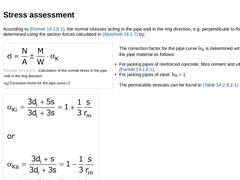
According to Formel 14.1.8.1, the normal stresses acting in the pipe wall in the ring direction, e.g. perpendicular to the pipe axis are determined using the section forces calculated in Abschnitt 14.1.7 by: (Formula: Calculation of the normal stress in the pipe wall in the ring direction)
The correction factor for the pipe curve αK is determined with reference to the pipe material as follows: - For jacking pipes of reinforced concrete, fibre cement …
|
|
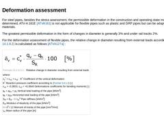
For steel pipes, besides the stress assessment, the permissible deformation in the construction and operating state must be determined, ATV-A 161E [ATVA161] is not applicable for flexible pipes such as plastic and GRP pipes but can be adapted for these materials. The greatest permissible deformation in the form of changes in diameter is generally 3% and under rail tracks 2%. For the deformation assessment of flexible pipes, the relative change in diameter … |

|
The assessment of safety against buckling, like the deformation assessment, is only necessary for flexible jacking pipes, i.e. pipes whose deformation substantially affects their carrying capacity. The bedding soil here is usually an important component of the carrier system. The critical buckling pressure pk is compared with the influences of vertical total load, maximum groundwater level and vacuum. If lubrication and support media have been injected … |
|
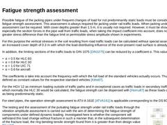
Possible fatigue of the jacking pipes under frequent changes of load for not predominantly static loads must be considered in the fatigue strength assessment. This assessment is always required for jacking under rail traffic loads. When jacking under roads, the assessment can be required. With cover depths greater than 1.5 m, it is usually not required. However, it must be shown that especially the section forces in the pipe wall from traffic loads, … |
|
|
|
The safety coefficients used in ATV-A 161E [ATVA161] have been determined based on the probabilistic reliability theory for pipes installed in the open cut method [Fuchs84]. Here the dispersion of the loading ability of the pipes (e.g. strength, dimensions) and the load (e.g. soil properties, traffic loads) have been taken into account. These safety coefficients can also be approximated for jacking pipes. Because of the different types of dispersions … |

|
Further loads on the pipes can be caused by unplanned deviations of technical influences or material properties. Among these especially are: - Exceeding and falling below the planned overcut
- Exceeding the deviations on which the dimensions are based with reference to the proposed line and gradient (line path).
- Exceeding the maximum permissible jacking forces
- Other jacking errors
- Deviations from the material properties and geometry (shape) of the pressure …
|
|
|
|
| (Image: Surface deformation in dependence on the support pressure or face resistance with reference to [ISEKI]) | | (Image: Surface deformation in dependence on the support pressure or face resistance with reference to [ISEKI]) |
The support force or the face resistance should be greater than the active earth pressure in order to prevent subsidence at the ground surface and should be less than the passive earth pressure in order to exclude heaving (Bild … |
|
|

|
According to Formel 14.2.2.1, the frictional resistance in jacking for planned straight line path is the result of the integration of the skin friction over the surface of the jacking or shield machine and the jacking pipes by: (Formula: Calculation of the frictional resistance) The determination of the skin friction is based on the laws of friction known from mechanics shown in Formel 14.2.2.1 : (Formula: Calculation of the skin friction) The coefficient … |
|
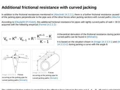
In addition to the frictional resistances mentioned in Abschnitt 14.2.2.1, there is a further frictional resistance caused by the loading of the jacking pipes perpendicular to the pipe axis of the drive forces when jacking sections with curved paths (Abschnitt 14.1.10). According to [Okada00] [FI-Kidoh], this additional frictional resistance for pipes with tightly curved paths of radii < 30 DN/OD is acquired with the following empirical Formel 14.2.2.2 |