|
For large borehole diameters and drilling in friable, non-stable soil, it can be necessary to carry out a socalled smoothing- or cleaning-run [HDD-58] (also called “check-Trip“ [HDD-94]) (cf. also (Calculations for the state of construction) Tip, (“Meeting-in-the-Middle“ technique) and (Crossing the Elbe River near St. Margarethen)). For this purpose a conical reamer without tooling with a final diameter of the borehole that is to be expanded is … |
|
Concerning the drilling tools, the following are differentiated in HDD depending on the working steps: -
drilling tools for pilot boring,
-
drilling tools for reaming(s),
-
drilling tools for borehole calibration,
-
drilling tools for smoothing the borehole.
|
|
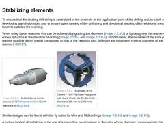
To ensure that the rotating drill string is centralized in the borehole at the application point of the drilling tool, to catch or prevent any developing lateral vibrations and to ensure quiet running of the drill string and directional stability, often additional measures are taken to stabilize the reaming. When using barrel reamers, this can be achieved by grading the diameter (Figure 47) or by designing the reamer with a strong coned reduction … |
|
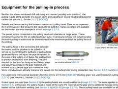
(Image: Pulling head fixed to a PVC-U-pipe DN/ID 300 with bolts)Besides the above mentioned drill rod string and reamer (possibly with stabilizer), the pulling-in pipe string consists of a swivel (joint) and a pulling or towing head (pulling grip for cables see Volume 1, Section 2.1.2.2 [HDD-1]). Swivels are the connecting link between reamer and pulling head. They serve to prevent the transmission of the torque to the pipe(s) to be pulled in. Various … |
|
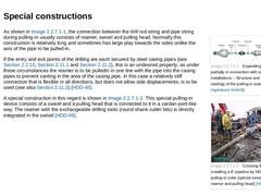
(Image: Expanding pulling heads, partially in connection with sealing installations – Structure and view (without sealing) of the pulling-in suite)As shown in Figure 53 a, the connection between the drill rod string and pipe string during pulling-in usually consists of reamer, swivel and pulling head. Normally this construction is relatively long and sometimes has large play towards the sides unlike the axis of the pipe to be pulled-in. If the entry … |
|
(Image: Pulling head fixed to a PVC-U-pipe DN/ID 300 with bolts)Besides the above mentioned drill rod string and reamer (possibly with stabilizer), the pulling-in pipe string consists of a swivel (joint) and a pulling or towing head (pulling grip for cables see Volume 1, Section 2.1.2.2 [HDD-1]). Swivels are the connecting link between reamer and pulling head. They serve to prevent the transmission of the torque to the pipe(s) to be pulled in. Various … |
|
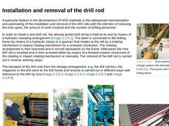
(Image: Semi automatic drill rod change system with steerable drill rod gripper – Placing the drill rod into the drilling frame)A particular feature in the development of HDD-methods is the widespread mechanisation and automating of the installation and removal of the drill rods with the intention of reducing the time spent, the amount of work involved and the number of drilling personnel. In order to install a new drill rod, the already jacked drill … |
|
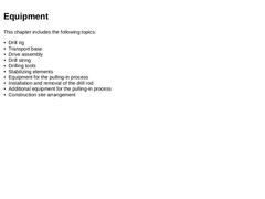
Depending on the construction task, various kinds of additional equipment are available to simplify and monitor the pulling-in process in practice, such as -
multiple clamps for group installation,
-
jacking station to support the pulling-in (or pushing-in) process with large steel pipes (“Pipe Thruster“),
-
measuring systems.
|
|
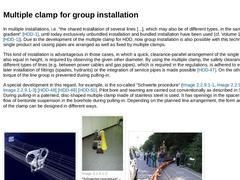
In multiple installations, i.e. “the shared installation of several lines [...], which may also be of different types, in the same line and gradient“ [HDD-1], until today exclusively unbundled installation and bundled installation have been used (cf. Volume 1, Section 2.2 [HDD-1]). Due to the development of the multiple clamp for HDD, now group installation is also possible with this technology. Here single product and casing pipes are arranged as … |
|
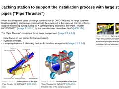
(Image: Jacking station of the type "Pipe-Thruster HK 250/500PT" – Functional principle of tandem)When installing steel pipes of a large nominal size (> DN/ID 700) and for large borehole lengths a jacking station can systematically be employed at the pipe exit point in order to support the drill rig during pulling-in. A corresponding example is the “Pipe Thruster HK250/500PT“ (Figure 65 a) by the manufacturer Herrenknecht AG [HDD-174]. The “Pipe Thruster“ … |
|
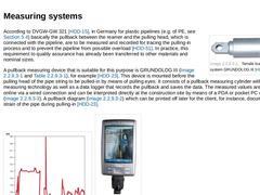
(Image: Tensile load measuring system GRUNDOLOG III – View)According to DVGW-GW 321 [HDD-15], in Germany for plastic pipelines (e.g. of PE, see (PE-pipes)) basically the pullback between the reamer and the pulling head, which is connected with the pipeline, are to be measured and recorded for tracing the pulling-in process and to prevent the pipeline from possible overload [HDD-51]. In practice, this requirement to quality assurance has already been … |
|
Depending on the construction task, various kinds of additional equipment are available to simplify and monitor the pulling-in process in practice, such as -
multiple clamps for group installation,
-
jacking station to support the pulling-in (or pushing-in) process with large steel pipes (“Pipe Thruster“),
-
measuring systems.
|
|
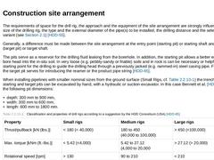
The requirements of space for the drill rig, the approach and the equipment of the site arrangement are strongly influenced by the size of the drilling rig, the type and the external diameter of the pipe(s) to be installed, the drilling distance and the selected pulling-in variant (see (Method of operation and sequence)) [HDD-55]. Generally, a difference must be made between the site arrangement at the entry point (starting pit) or starting shaft … |
|
|
|
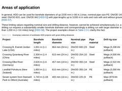
In general, HDD can be used for borehole diameters of up 2200 mm (≈ 86 in.) (max. nominal pipe size PE: DN/OD 1400 (1500), steel: DN/OD 820, cast: DN/OD 842 [HDD-5]) with pipe lengths up to 3,000 m in soils and rock with and without groundwater [HDD-57]. These limiting values regarding nominal size and drilling distance, however, cannot be achieved simultaneously (i.e. a very long drilling run requires a substantially smaller borehole diameter and … |
|
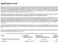
Because of the variety in drilling tools, the application of these tools, the methods and parameters of drilling, the characteristics of drilling fluid and fluid pressures and their possible combinations, HDD has a wide area of application in soils and rock. According to [HDD-61], they are basically suitable for application in organic (Class LO) as well as in cohesive and noncohesive soils of Classes LB and LN according to DIN 18319 [HDD-62] or in … |
|
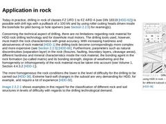
(Image: Difficulty levels when using HDD in rock – case examples for different subsoil conditions)Today in practice, drilling in rock of classes FZ 1/FD 1 to FZ 4/FD 4 (see DIN 18319 [HDD-62]) is possible with drill rigs with a pullback of ≥ 100 kN and by using roller cutting heads driven inside the borehole for pilot boring or hole openers (see (Drilling tools)) for reaming(s). Concerning the technical aspect of drilling, there are no limitations … |

|
In general, HDD can be used for borehole diameters of up 2200 mm (≈ 86 in.) (max. nominal pipe size PE: DN/OD 1400 (1500), steel: DN/OD 820, cast: DN/OD 842 [HDD-5]) with pipe lengths up to 3,000 m in soils and rock with and without groundwater [HDD-57]. These limiting values regarding nominal size and drilling distance, however, cannot be achieved simultaneously (i.e. a very long drilling run requires a substantially smaller borehole diameter and … |
|
HDD used in trenchless installation is counted among the near-surface directional drilling methods. While drilling, its spatial path is controlled and, if necessary, directionally oriented or influenced by means of technical or technological measures for the purpose of corresponding to the planned drilling profile [HDD-67] [HDD-68]. This influencing not only includes the maintenance of the prescribed drilling profile, but also the correction of natural … |

|
The following components are used for both variants of the measuring system: - transmitter (sonde, probe, beacon),
- receiver (with display and data logger, where necessary),
- data display device (monitor).
|
|
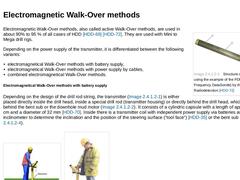
(Image: Structure of a transmitter using the example of the PDF (Precision Dual Frequency DataSonde) by the company Radiodetection)Electromagnetic Walk-Over methods, also called active Walk-Over methods, are used in about 90% to 95 % of all cases of HDD [HDD-69] [HDD-72]. They are used with Mini to Mega drill rigs. Depending on the power supply of the transmitter, it is differentiated between the following variants: -
electromagnetical Walk-Over methods …
|
|
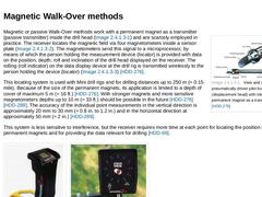
(Image: View and structure of the pneumatically driven pilot boring head (displacement head) with integrated permanent magnet as a transmitter)Magnetic or passive Walk-Over methods work with a permanent magnet as a transmitter (passive transmitter) inside the drill head (Figure 83) and are scarcely employed in practice. The receiver locates the magnetic field via four magnetometers inside a sensor plate (Figure 84 a). The magnetometers send this … |

|
The following components are used for both variants of the measuring system: - transmitter (sonde, probe, beacon),
- receiver (with display and data logger, where necessary),
- data display device (monitor).
|
|
The Wire-Line method is a locating technique with cable (direct) based on the natural terrestrial magnetic field or, if required, based on an artificially generated magnetic field. It originates from deep drilling technology and is mainly used with large drill rigs and correspondingly long and deep drillings. The most important system components are: -
non-magnetic drill rod with sensors and transmitter,
-
data transmitting cable,
-
steering desk.
Sensors … |
|
The following locating techniques, for example, belong to alternative locating techniques that are only employed in major drilling technology: -
gyroscope,
-
parallel bore measuring method,
-
positioning of a magnetic field sensor in the environment of the drill path.
DWA-A 125 [HDD-10] recommends to employ a gyroscope or gyro compass or the parallel bore measuring method in hardly accessible or non-accessible areas with strong magnetic interferences. |