|
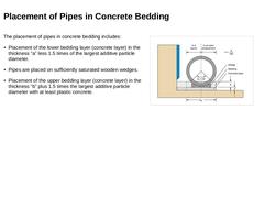
The placement of pipes in concrete bedding includes: -
Placement of the lower bedding layer (concrete layer) in the thickness “a” less 1.5 times of the largest additive particle diameter.
-
Pipes are placed on sufficiently saturated wooden wedges.
-
Placement of the upper bedding layer (concrete layer) in the thickness “b” plus 1.5 times the largest additive particle diameter with at least plastic concrete.
(Image: Installation of a reinforced concrete … |

|
In the case of concrete pipes with an integrated base, the base takes over the function of the upper bedding layer. Therefore, they can usually be placed directly on a prepared, horizontally levelled and compacted bedding of suitable soil material (lower bedding layer), directly on the prepared trench base or on a concrete support. Even with these type of pipes, it is necessary to compact the haunch areas by hand to ensure proper compaction. For placement … |
|
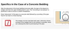
(Image: Installation of a reinforced concrete pipe on a concrete base in accordance with) After the placement of the lower bedding (concrete slab), the pipe is first placed on wedges and then the upper bedding layer is cast. This "concreting in two phases" is practiced in order to ensure a uniform embedment. Direct “placement" of the pipe on a concrete slab followed by concreting of the pipe haunch can lead to a linear bearing! |
|
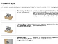
In the structural calculation of the pipe, the pipe bedding is defined by the "placement method" and the "bedding angle" [ATVA127]. |
(Image: Storage Case I - support in the soil ("Loose bearing")) |
Placement type I - Placement on soil ("Loose bearing") |
Vertically oriented rectangular distributed forces. This case applies to the stress analysis and elongation detection (short-term and long-term) for rigid and flexible pipes. The support angle for … |
|
|
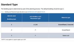
The bedding type is determined as part of the planning process. The default bedding should be type 1. (Table: Bedding and Placement type allocation as per DIN EN 1610 and ATV-DVWK-A 127) |
|
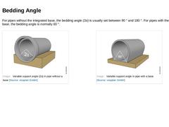
For pipes without the integrated base, the bedding angle (2α) is usually set between 90 ° and 180 °. For pipes with the integrated base, the bedding angle is normally 60 °. (Image: Variable support angle (2α) in pipe without a base) (Image: Variable support angle in pipe with a base) |
|
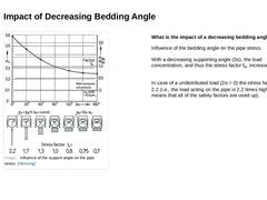
(Image: Influence of the support angle on the pipe stress) What is the impact of a decreasing bedding angle? Influence of the bedding angle on the pipe stress.
With a decreasing supporting angle (2α), the load concentration, and thus the stress factor fA, increases.
In case of a undistributed load (2α = 0) the stress factor is fA = 2.2 (i.e., the load acting on the pipe is 2.2 times higher, this means that all of the safety factors are used up).
|
|
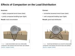
Incorrect: Result: load concentration Correct: Result: good load distribution (Image: Load concentration due to an unfavorable compaction ratio between the trench base and subbase) (Image: Good load distribution as a result of a favourable compaction ratio between the trench base and subbase) |

|
(Image: Effects of uneven longitudinal load distribution) What kind of impact have highly compacted bedding areas? Highly compacted areas within the bedding layer lead to the formation of point loads (shown dotted thickly here) resulting in the cracking of the pipe. |

|
|

|
Congratulations! You have successfully finished this module. Next, you will have the opportunity to review the newly acquired knowledge with an interactive questionnaire. You can, of course, still navigate back to any point in the modules if you wish to review a specific subject. Stay curious! |
|
The embedment consists of bedding, side filling and initial and main cover. The quality of the embedment is significantly influenced by the installation conditions of the pipes. Other topics of this module include flowable fill for trench backfill, optimized installation methods and compaction tests. After completing this module, you will have a sound knowledge of: - rules and regulations;
- requirements for the embedment zone and compaction of the trench backfill;
- process sequences of the open cut method;
- influencing factors to ensure high execution quality on the construction site;
- recognizing and assessing errors in construction.
|
|
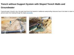
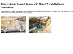
If ground water is found in situ, the water level has to be lowered or additional waterproofing measures have to be taken in order to prevent water from leaking through the slopes [Schne95]. (Image: Groundwater lowering using vacuum drainage (deep well system) – Detail header pipe) (Image: Excavation with poorly sloped trench (danger to life) and unqualified form of groundwater lowering (danger to life) and unqualified form of groundwater lowering) |
|
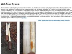
The installation method (jetting, insertion into boreholes, etc.) for the well-points is highly dependent on the subsoil conditions. The pictures show well-points in the form of self-jetting well-point. The self-jetting well-points are installed using high-pressure water supplied to the top of the riser pipe from a water jetting pump. At the tip of the self-jetting well-point below the wellpoint screen, there is a hollow jetting shoe. Near the lower … |
|
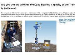
The compaction of the trench base must be coordinated with the compaction of the bedding layers. The compaction of the trench base should not be excessive, as the subsequent compaction of the haunch area must be at least as good as that of the lower bedding layer or the trench base, in order to avoid a reduction of the effective support angle and thus an overloading of the pipes. (Image: Verification of the bearing capacity of the trench base by means … |
|
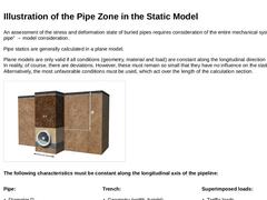
An assessment of the stress and deformation state of buried pipes requires consideration of the entire mechanical system "road-soil-pipe" → model consideration. Pipe statics are generally calculated in a plane model. Plane models are only valid if all conditions (geometry, material and load) are constant along the longitudinal direction of the pipeline. In reality, of course, there are deviations. However, these must remain so small that they have … |

|
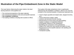
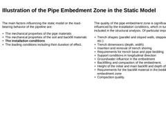
The main factors influencing the static model or the load-bearing behavior of the pipeline are: -
The mechanical properties of the pipe materials
-
The mechanical properties of the soil and backfill materials
-
The installation conditions
-
The loading conditions including their duration of effect.
The quality of the pipe embedment zone is significantly influenced by the installation conditions, which in turn must be included in the structural analysis. … |

|
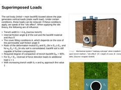
The soil body (initial + main backfill) located above the pipe generates vertical loads (static earth load). Under certain conditions, these loads can be reduced. If these conditions apply, we speak of the "silo effect". When applying the silo theory, the following are of influence: -
Trench width b < 4 da (narrow trench)
-
Internal friction angle ϕ of the soil and the backfill material and thus δ
-
The cover filling conditions A, which depends on the …
|
|
The soil body (initial + main backfill) located above the pipe generates vertical loads (static earth load). Under certain conditions, these loads can be reduced. If these conditions apply, we speak of the "silo effect". When applying the silo theory, the following are of influence: -
Trench width b < 4 da (narrow trench)
-
Internal friction angle ϕ of the soil and the backfill material and thus δ
-
The cover filling conditions A, which depends on the …
|

|
What needs to be done to verify the load bearing system? |

|
What needs to be done to verify the load bearing system? |
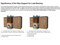
|
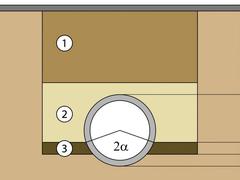
The vertical loads acting on the pipe must be transferred to the ground. This transfer is performed by the pipe support. The pipe support is described by the support angle 2 α (alpha). The larger the support angle 2α, the better the support. The illustration shows a support angle with 2 α = 90, i.e. α = 45. In addition to the size of the support angle, another important quality feature of the support is the uniformity or homogeneity of the compaction … |