|
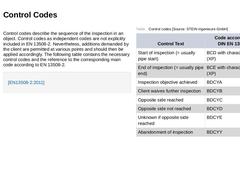
Control codes describe the sequence of the inspection in an object. Control codes as independent codes are not explicitly included in EN 13508-2. Nevertheless, additions demanded by the client are permitted at various points and should then be applied accordingly. The following table contains the necessary control codes and the reference to the corresponding main code according to EN 13508-2. |
|
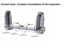
(Image: Example: Control codes - cancellation of an inspection) |
|
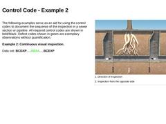
The following examples serve as an aid for using the control codes to document the sequence of the inspection in a sewer section or pipeline. All required control codes are shown in bold/black. Defect codes shown in green are exemplary observations without quantification. Example 2: Continuous visual inspection. Data set: BCDXP.....BBAA.....BCEXP (Image: Control code - visual inspection image 1) |
|
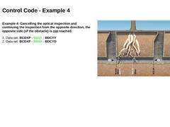
Example 4: Cancelling the optical inspection and continuing the inspection from the opposite direction, the opposite side (of the obstacle) is not reached. 1. Data set: BCDXP - BBAA - BDCYY
2. Data set: BCDXP - BBAA - BDCYD (Image: Control code - visual inspection image 3) |
|
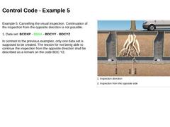
Example 5: Cancelling the visual inspection. Continuation of the inspection from the opposite direction is not possible. 1. Data set: BCDXP - BBAA - BDCYY - BDCYZ In contrast to the previous examples, only one data set is supposed to be created. The reason for not being able to continue the inspection from the opposite direction shall be described as a remark on the code BDC YZ. (Image: Control code - visual inspection image 4) |
|
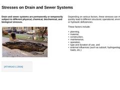
Drain and sewer systems are permanently or temporarily subject to different physical, chemical, biochemical, and biological stresses. (Image: Street collapse caused by leakiness) Depending on various factors, these stresses can more or less quickly lead to different structural, operational, environmental, or hydraulic deficiencies. These factors include: -
planning,
-
material,
-
construction,
-
maintenance,
-
operation,
-
type and duration …
|
|
|
Step 1 |
Step 2 |
Step 3 |
Step 4 |
Step 5 |
|---|
|
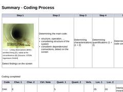
(Image: Lining observations wrinkled lining radial at the circumference) Detect findings on the screen |
Determining the main code: -
structure, operation, ...
-
considering structure of the system
-
considerin dependencies/connections, detect on the screen
|
Determining
characterisations (1 + 2) |
Determining quantifications (1 + 2) |
Determining all other code components |
Coding completed |
|
Sewer systems are either permanently or temporarily subject to different physical, chemical, biochemical and biological forms of stress. Depending on the -
Planning and design,
-
Material,
-
Construction,
-
Maintenance (and repair),
-
Operation,
-
Type and duration of use as well as
-
External effects (such as subsoil, hydrogeology, traffic load and the like),
these stresses can more or less rapidly result in different structural, operational, environmentally … |

|
|
|
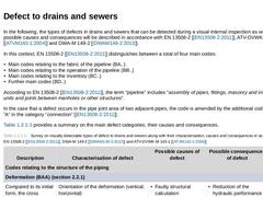
In the following, the types of defects in drains and sewers that can be detected during a visual internal inspection as well as their possible causes and consequences will be described in accordance with EN 13508-2 [ [EN13508-2:2011]], ATV-DVWK-M 143-1 [ [ATVM143-1:2004]] and DWA-M 149-2 [ [DWAM149-2:2013]]. In this context, EN 13508-2 [ [EN13508-2:2011]] distinguishes between a total of four main codes: -
Main codes relating to the fabric of the pipeline (…
|
|
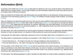
According to EN 13508-2 [ [EN13508-2:2011]], deformation is defined as “the cross-sectional shape of the pipeline has been deformed from its original shape”. For this type of defect, the client will define whether this code must only be used for flexible pipes or for pipes made of all kinds of material. Pipes are defined to be flexible when their deformation has essential effects on the distribution of loads and pressure, as the soil is a component … |
|
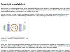
According to the definitions mentioned above, the classification as either flexible or rigid pipe always has to be made taking the soil consistency into account. Thus, it is rather a categorisation of the entire system composed of the stiffness of the pipe and soil consistency than a mere assessment of the stiffness of the pipe. In order to ensure the load transfer as a pipe-soil-system, the stiffness of the pipe has to provide for both a consistent … |
|
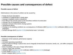
Possible causes of defect Deformations in the sense of a defect can be caused by: -
Faulty structural calculations
-
Installation of inappropriate or faulty pipes
-
Improper installation and/or embedment
-
Poor filling of the annular space in the trenchless method of construction
-
Improper use of compacting machines
-
Improper removal of the trench shoring systems
-
Temperature effects
-
Changes in the bedding conditions as a consequence of infiltration (…
|
|
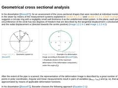
In his dissertation [ [Bosse97]], for an assessment of the cross-sectional shapes that were recorded at individual monitoring stations in the sewer by means of the measurement systems explained in section 4.1.3.1.3 and section 4.1.3.1.4 (both in progress), Bosseler suggests a circular ring with a negligibly small wall thickness d as the undeformed initial system. In the plane, each point P on the circumference of the circle has two degrees of freedom … |
|
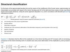
On the basis of the approximated bending line and by means of the coefficients of the Fourier series, approximation possibilities for interpretation are provided with regard to the interior bending work Wi of the deformed linear-elastic circular ring (Remember: work is equal to force times distance). Using the series approach (Equation 2‑1), and in accordance with Bosseler [ [Bosse97]], this can be calculated as follows: (Formula: Bending approach … |
|
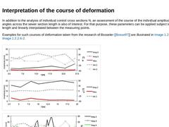
In addition to the analysis of individual control cross sections N, an assessment of the course of the individual amplitudes and phase angles across the sewer section length is also of interest. For that purpose, these parameters can be applied subject to the line length and linearly interpolated between the measuring points. Examples for such courses of deformation taken from the research of Bosseler [ [Bosse97]] are illustrated in Image 2‑25 and |
|
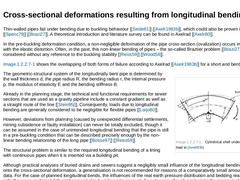
Thin-walled pipes fail under bending due to buckling behaviour [ [Seide61]] [ [Axelr1983b]], which could also be proven in test series [ [Spenc79]] [ [Brazi27]]. A theoretical introduction and literature survey can be found in Axelrad [ [Axelr80]]. In the pre-buckling deformation condition, a non-negligible deformation of the pipe cross-section (ovalization) occurs in conjunction with the elastic distortion. Often, in the past, this non-linear bending … |
|
As described in (Vertical cracks (longitudinal cracks)), at present, there are only very sketchy suggestions with regard to the classification of deformations for flexible pipes. These are generally limited to the parameter of the vertical deformation dv and consider deformations that are larger than planned in the structural design as descriptions of damage. In (Geometrical cross sectional analysis), the related types of misinterpretation, which … |
|
|
|
According to EN 13508-2 [ [EN13508-2:2011]], the description of a defect fissure (crack) mostly occurs for rigid pipes. The formation of fissures is characterised subject to the nature of the fissures and their orientation, whereby it is distinguished between the following types of fissures that can be the precursors for pipe fractures and the subsequent collapse of a sewer ( (Break / Collapse (BAC))): -
Surface crack (hairline crack) (code specification …
|
|
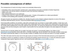
The consequences of cracks occurring in sewers are essentially influenced by: -
Orientation of the crack (horizontal / inclined crack, crack starting at one point or formation of broken fragments)
-
Depth of the crack (at the surface or through the wall of the structural component)
-
Width of the crack
-
Pipe material (reinforced or non-reinforced)
-
Position of the crack (in or above the water-bearing area) – Position of the pipeline (in or above groundwater)
|
|
|
|
According to EN 13508-2 [ [EN13508-2:2011]], pipe break or collapse is defined as the displacement of pipe segments (pieces) and missing of individual, more or less large segments (pieces) of the pipe wall ( (Descriptions of defect, possible causes and consequences of defect) on the following page). Collapse, also according to EN 13508-2 [ [EN13508-2:2011]], is understood to be the total loss of structural integrity combined with a breakdown of the … |
|
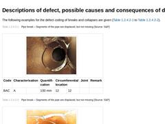
The following examples for the defect coding of breaks and collapses are given (mage 2‑43 to Image 2‑48). (Table: Pipe break – Segments of the pipe are displaced, but not missing) (Table: Pipe break – Segments of the pipe are displaced, but not missing) (Table: Pipe break – Segments of the pipe are displaced, but not missing) (Table: Pipe break – Missing parts in the pipe wall) (Table: Pipe break – Pipe segments are displaced, but not missing and missing … |
|
|