|
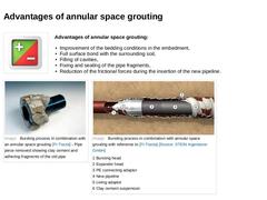
(Image: Plus/Minus Icon) Advantages of annular space grouting: -
Improvement of the bedding conditions in the embedment,
-
Full surface bond with the surrounding soil,
-
Filling of cavities,
-
Fixing and sealing of the pipe fragments,
-
Reduction of the frictional forces during the insertion of the new pipeline.
(Image: Bursting process in combination with an annular space grouting [FI-Tracta] - Pipe piece removed showing clay cement and adhering fragments … |
|
|

|
Question: Upon which factors is the required bursting force dependant? 1st Factor
Tip: Pipe material (Image: Fragezeichen) 2nd Factor
Tip: Soil condition (Image: Fragezeichen) 3rd Factor
Tip: Bursting unit (Image: Fragezeichen) |
|
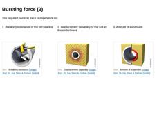
The required bursting force is dependant on: 1. Breaking resistance of the old pipeline 2. Displacement capability of the soil in the embedment (Image: Breaking resistance) (Image: Displacement capability) (Image: Amount of expansion) |
|
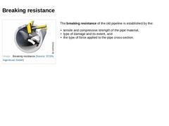
(Image: Breaking resistance) The breaking resistance of the old pipeline is established by the: -
tensile and compressive strength of the pipe material,
-
type of damage and its extent, and
-
the type of force applied to the pipe cross-section.
|
|
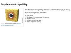
(Image: Displacement capability) The displacement capability of the soil is established mostly by its density. Main influencing factors include the: -
type of soil,
-
density and consistency of the layers,
-
depth of cover,
-
primary stress level, and
-
stress and strain history.
|
|
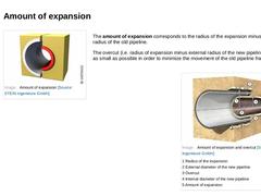
(Image: Amount of expansion) The amount of expansion corresponds to the radius of the expansion minus the internal radius of the old pipeline. The overcut (i.e. radius of expansion minus external radius of the new pipeline) should be as small as possible in order to minimize the movement of the old pipeline fragments. (Image: Amount of expansion and overcut) |

|
In determining the amount of expansion, the following questions must be answered while taking into account the existing soil conditions: -
What amount of energy is justifiable with regards to the resulting vibrations?
-
Which soil deformations and the resulting heaving or settling of the surface are justifiable?
In order to prevent heaving or settling at the surface, a minimum pipeline depth of cover of 10 x the amount of expansion has proven to be … |
|
According to DWA-M 143-15 [DWAM143-15:2005], a buffer between parallel pipelines of at least three times the amount of expansion (minimum 40 cm) has proven to be effective for cohesive soils. (Image: Fragezeichen) Example calculation for the amount of expansion in cohesive soils: Diameter of the old pipeline: DN 250
Diameter of the new pipeline: DN 280
External diameter of the expansion: DN 340 Calculation according to DWA-M 143-15: 3 x (340 mm -– 250 … |
|
For non-cohesive and/or stony soils special considerations apply which concern the diameter and the material of the neighbouring pipelines. For pipe materials < DN 200 that are brittle and easy to break, the minimum spacing should be at least 5 times the amount of expansion. For nominal sizes > DN 200, the spacing should not be less than 1.0 m. (Image: Fragezeichen) Example calculation for the amount of expansion in non-cohesive soils: Neighbouring … |
|
For non-cohesive and/or stony soils special considerations apply which concern the diameter and the material of the neighbouring pipelines. For pipe materials < DN 200 that are brittle and easy to break, the minimum spacing should be at least 5 times the amount of expansion. For nominal sizes > DN 200, the spacing should not be less than 1.0 m. Example calculation:
5 x (340 mm – 250 mm) = 0,45 m < min. 1.00 m
The calculated distance … |
|
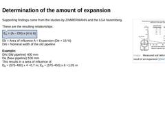
(Image: Measured soil deformation as a result of an expansion [Zimme88]) Supporting findings come from the studies by ZIMMERMANN and the LGA Nuremberg. These are the resulting relationships: Eb = (A – DN) x (4 to 6) Eb = Area of influence A = Expansion (De + 15 %)
DN = Nominal width of the old pipeline Example:
DN (Old pipeline) 400 mm
De (New pipeline) 500 mm
This results in a area of influence of
Eb = (575-400) x 4 =0,7 m; Eb = (575-400) x 6 =1.05 m… |

|
|

|
|

|
The minimum distances to neighbouring utilities and structures depend on: -
Displacement properties of the surrounding soil,
-
The rate of expansion,
-
Material type and bedding/foundations of the neighbouring utilities and structures.
In case that minimum distances cannot be adhered to, special protective measures, such as open cut excavation at the crossing points, must be taken in order to prevent the transfer of loads. (Image: Underground utilities … |
|
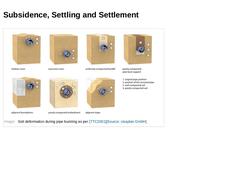
Soil deformation is generally understood to be the horizontal or vertical positional change of the soil surface or a point inside the soil. Vertical soil deformation in the direction of the ground surface is called heaving and in the opposite direction it is referred to as subsidence, settling or settlement. |
|
Subsidence is understood to be the vertical displacement of an entire soil stratum as a result of the movement of soil at a great depth. In this case, the size of the displacement can be determined but not its timing [Schmi96]. Settling occurs in granular soils due to a sudden rearrangement of the grain particles caused by the addition of water. For loosely compacted soils, this settling can amount to 5 % of the layer thickness, and for densely compacted … |
|
(Image: Soil deformation during pipe bursting as per [TTC2001]) |

|
|
|
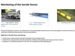
(Image: Target manhole - capstan winch) (Image: Overload protection [Jürge05]) During the pulling-in process, the adherence to the permissible tensile forces on the new pipeline must be ensured by means of continual monitoring (measurement and documentation). Methods of tensile force monitoring: -
Tensile force measurement and documentation at the pulling device
-
Tensile force measurement and documentation directly at the pulling …
|
|
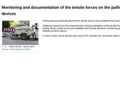
(Image: Target manhole - capstan winch) Pulling devices automatically limit the tensile force to the predetermined maximum value. Additional systems for the measurement and documentation of the tensile forces on the pulling device (cable winch) are available and include electronic monitoring gauges and detailed printout reports. In some cases, these devices also have a PC interface for convenient data transfer. |
|
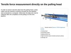
In order to receive real time data from the pulling head, a data cable must be inserted in advance through the new pipeline and connected to a computer. Otherwise, the data can only be collected after the completion of the pulling-in of the new pipeline. |
|
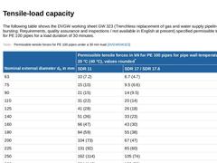
The following table shows the DVGW working sheet GW 323 (Trenchless replacement of gas and water supply pipelines with pipe bursting; Requirements, quality assurance and inspections / not available in English at present) specified permissible tensile forces for PE 100 pipes for a load duration of 30 minutes. (Table: Permissible tensile forces for PE 100 pipes under a 30 min load [DVGWGW323]) |
|
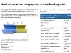
According to GW 323-4.3.2, the breaking strength of HD-PE is 2.5 times the permissible tensile stress [DVGWGW323]. The cross sectional area of a pipe section used as overload protection may only amount to 40 % of the cross sectional area of the new pipeline being pulled in. (Image: Overload protection in form of a predetermined breaking point by reduction of the wall thickness) (Table: Example calculation of an overload protection for HD-PE 100 used … |
|
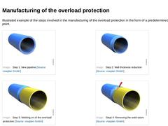
Illustrated example of the steps involved in the manufacturing of the overload protection in the form of a predetermined breaking point. (Image: Step 1: New pipeline) (Image: Step 2: Wall thickness reduction) (Image: Step 3: Welding on of the overload protection) (Image: Stept 4: Removing the weld seam) |